Externally-mounted sub-spindle

A plug-in, spindle technology, applied in the direction of large fixed members, metal processing machinery parts, metal processing equipment, etc., can solve the problems of low demand for linear motor machine tools, small market demand, and high equipment cost, etc., to achieve Solve the accuracy requirements and efficiency problems, easy to adjust and control, and low maintenance cost

Inactive Publication Date: 2014-08-27
NEUTRON SHANGHAI
View PDF8 Cites 0 Cited by
  • Summary
  • Abstract
  • Description
  • Claims
  • Application Information

AI Technical Summary

Problems solved by technology

However, the current market share of this kind of CNC machine tool is high, and most of the market tasks can be achieved. It is not time to replace it with a linear motor high-speed spindle machine tool. Moreover, the price of linear motor equipment is high. The processing technology in the current market is not suitable for The demand for linear motor machine tools is not very large
[0003] In addition, the current equipment market already has equipment that uses linear motors to drive the movement of each axis or is equipped with high-speed spindles (above 30,000 rpm), but the equipment is extremely expensive and has poor versatility. The industry is temporarily unable to use it on a large scale.
[0004] Due to the current environment of the processing and manufacturing industry, traditional equipment has a large market share, but it is not conducive to meeting the existing high machining accuracy and requirements. Although the accuracy of linear motor equipment or high-speed spindles can be guaranteed, and some special equipment can be achieved Processing requirements, but there are disadvantages such as high price, poor versatility, and small market demand

Method used


Image

  • Externally-mounted sub-spindle
  • Externally-mounted sub-spindle
  • Externally-mounted sub-spindle

Examples


Embodiment 1

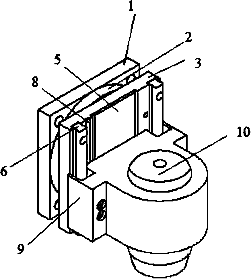
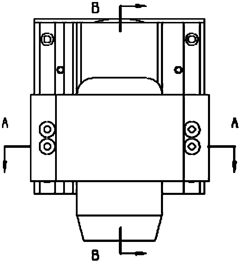
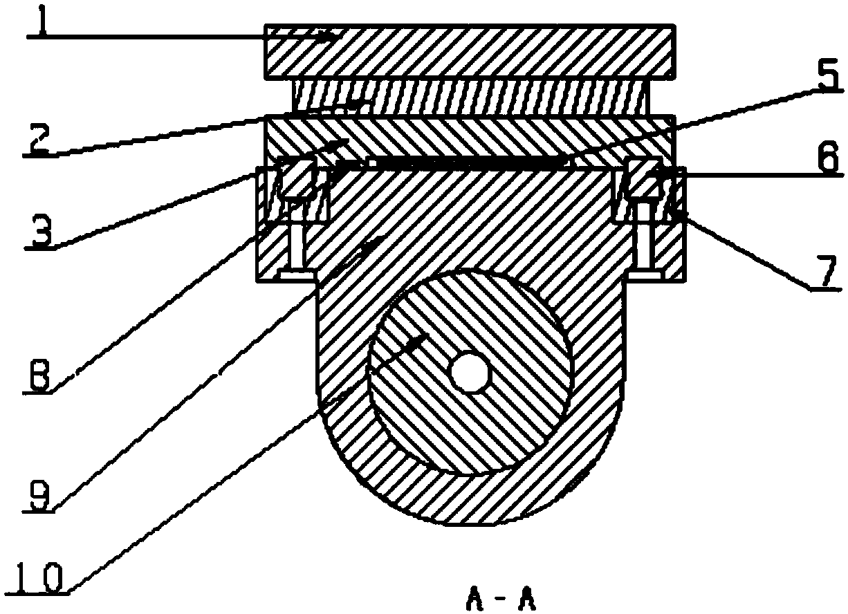
[0032] Such as Figure 1-5 As shown, an externally mounted sub-spindle can be used alone or in conjunction with traditional mechanical equipment, for example, through the Z-axis screw drive movement of the CNC machine tool itself or equipped with a linear motor for independent movement. In this embodiment, the external sub-spindle is used in combination with a CNC machine tool. The CNC machine tool includes a machine bed 101, a workbench 102 and a main shaft 103. The external sub-spindle 104 is installed on the main shaft 103 of the CNC machine tool. The external hanging sub-spindle 104 includes a fixed connection plate 1, an adjustable index plate 2, a sliding backing plate 3, a precision guide rail 6, a linear slider 7, a main shaft mounting seat 9, and a high-speed main shaft 10; The connecting plate 1 is fixed on the main shaft 103 by bolts or magnetic force. The adjustable indexing plate 2 and the sliding backing plate 3 are sequentially arranged on the installation and ...


PUM


Abstract

The invention relates to an externally-mounted sub-spindle. The externally-mounted sub-spindle is an independent product and can be sold independently, used independently or combined with other machine devices to be used. The externally-mounted sub-spindle structurally comprises a fixed connecting plate (1), an adjustable indexing disc (2), a sliding base plate (3), a precise guide rail (6), a linear sliding block (7), a spindle mounting seat (9) and a high-speed spindle (10). The fixed connecting plate (1) is fixedly arranged on a spindle (103), the adjustable indexing disc (2) and the sliding base plate (3) are arranged on the fixed connecting plate (1) in sequence, the precise guide rail (6) is arranged on the sliding base plate (3), the spindle mounting seat (9) is arranged on the precise guide rail (6) through the linear sliding block (7), and the high-speed spindle (10) is arranged on the spindle mounting seat (9). Compared with the prior art, the externally-mounted sub-spindle has the advantages of being high in efficiency, simple in structure, convenient to use and the like.

Description

technical field [0001] The invention relates to an externally mounted sub-spindle, in particular to an externally mounted sub-spindle as an independent product, which can be sold separately, used alone or combined with other mechanical equipment. Background technique [0002] At present, the driving mode of the Z-axis of CNC machine tools is mostly driven by a motor to drive the screw to realize the movement of the Z-axis, and most of the spindles are low-number spindles (below 20,000 rpm). Limited to the screw transmission of existing CNC machine tools, the disadvantages caused by the defects of the screw cannot be avoided during use, such as jitter, backlash error, temperature rise, slow acceleration, and high-speed linear motion cannot be avoided. However, low-number spindles cannot complete some special processes and achieve special processing effects. However, the current market share of this kind of CNC machine tool is high, and most of the market tasks can be achieve...

Claims


Application Information

Patent Timeline
IPC IPC(8): B23Q5/32B23Q1/25
CPCB23Q5/32
Inventor 刘俊达
Owner NEUTRON SHANGHAI
Why Eureka
Try Eureka