
Method, system and apparatus for fault detection

a fault detection and fault technology, applied in the field of power transmission systems, can solve the problems of serious trouble for distance protection, inability to detect faults, and inability to detect faults, and achieve the effect of strong resistan

Pending Publication Date: 2019-09-26
HITACHI ENERGY LTD
View PDF1 Cites 8 Cited by
  • Summary
  • Abstract
  • Description
  • Claims
  • Application Information

AI Technical Summary

Benefits of technology

The present invention is a new method for measuring distance using a time-domain approach. The measurement is done by comparing the voltage levels of two signals. This method is stronger against certain types of harmonics and can handle high frequency harmonics. This change in format makes it easier to use the distance relay for protection purposes.

Problems solved by technology

However, the distance protection of prior art may mal-operate because of harmonics.
Especially when the distance relay is used in the series-compensated line, besides high frequency components and DC components, there are low frequency components which bring serious trouble to distance protection.
The distance protection may overreach because of low frequency components.
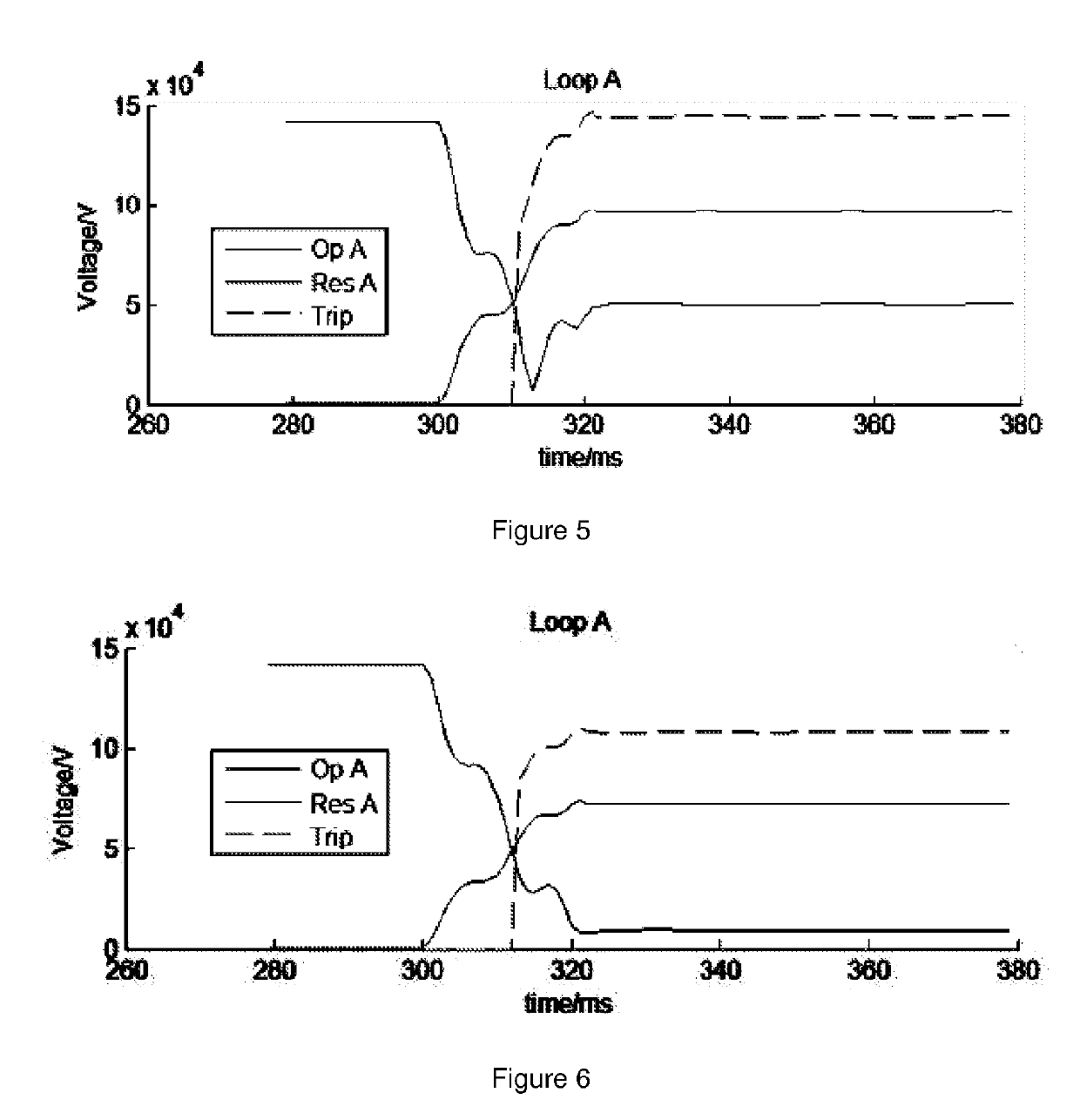
The simulation results show that the distance protection of prior art may overreach because of external faults.

Method used

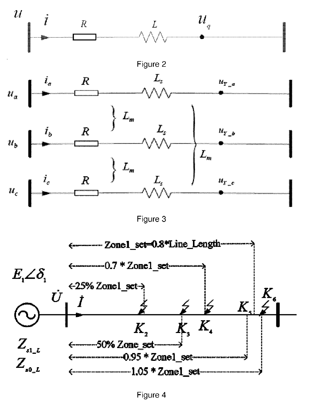

Image

  • Method, system and apparatus for fault detection
  • Method, system and apparatus for fault detection
  • Method, system and apparatus for fault detection

Examples


Embodiment Construction

[0087]Hereinafter, the present invention is further described in detail by the way of the particular embodiments in combination with the figures.

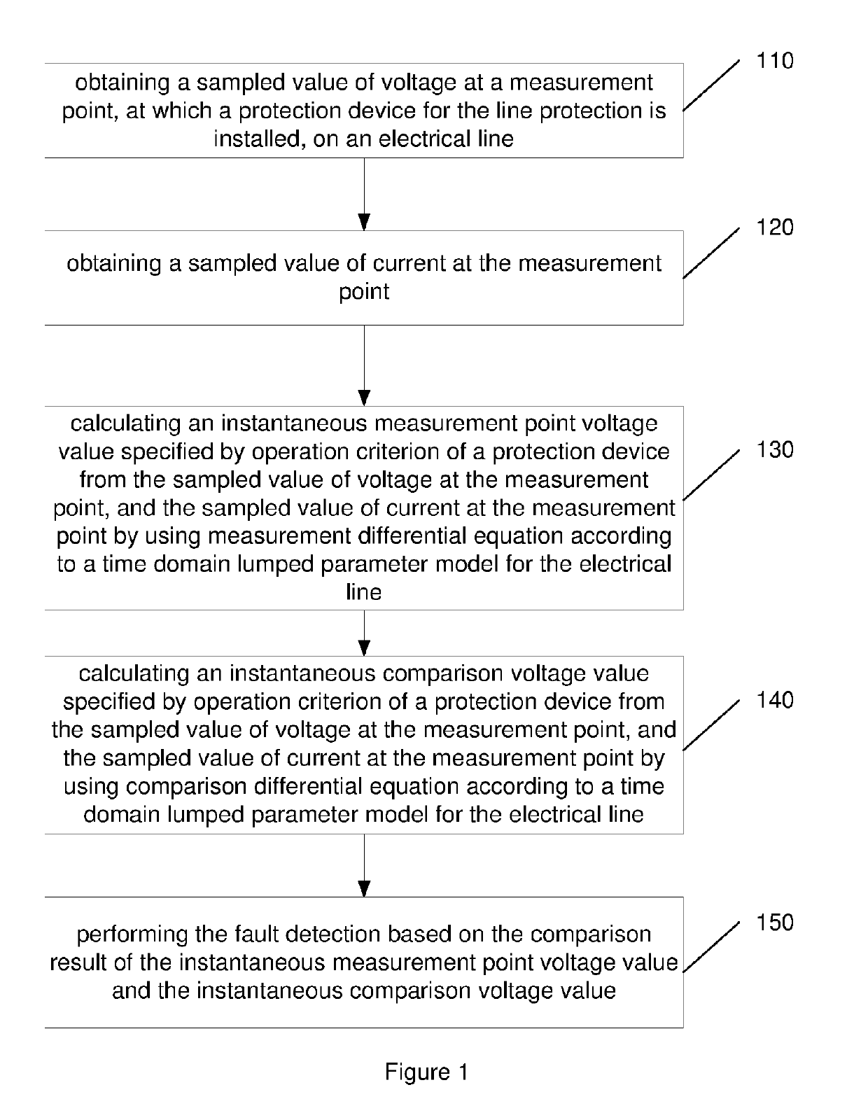
[0088]FIG. 1 shows a flow-process diagram illustrating a method for fault detection in line protection for power transmission system, comprising the following steps:[0089]step 110, obtaining a sampled value of voltage at a measurement point, at which a protection device for the line protection is installed, on an electrical line;[0090]step 120, obtaining a sampled value of current at the measurement point;[0091]step 130, calculating an instantaneous measurement point voltage value specified by operation criterion of a protection device from the sampled value of voltage at the measurement point, and the sampled value of current at the measurement point by using measurement differential equation according to a time domain lumped parameter model for the electrical line;[0092]step 140, calculating an instantaneous comparison voltage value speci...


PUM


Abstract

A method, system and apparatus for fault detection in line protection for a power transmission system. The method includes: obtaining a sampled value of voltage at a measurement point, at which a protection device for the line protection is installed, on an electrical line; obtaining a sampled value of current at the measurement point; calculating an instantaneous measurement point voltage value specified by operation criterion of a protection device from the sampled value of voltage at the measurement point and the sampled value of current at the measurement point by using measurement differential equation according to a time domain lumped parameter model for the electrical line; calculating an instantaneous comparison voltage value specified by operation criterion of a protection device from the sampled value of voltage at the measurement point and the sampled value of current at the measurement point by using comparison differential equation according to a time domain lumped parameter model for the electrical line; and performing the fault detection based on the comparison result of the instantaneous measurement point voltage value and the instantaneous comparison voltage value. The method transfers the distance relay to the format of voltage comparison, calculate the voltage using differential equation instead of vector, and compare the amplitude of calculated voltages. It designs a time-domain distance protection which has strong ability to resist DC components and harmonics including high frequency harmonic and low frequency harmonic.

Description

TECHNICAL FIELD[0001]The present application relates to a method, system and apparatus for fault detection in line protection for a power transmission system.BACKGROUND ART[0002]Distance protection is one of line protection technologies, which could determine a distance between a fault point and a point at which a protection device is installed and the time for actions based on the determined distance. The distance protection is one of the most important protections for extra / ultra-high voltage (EHV / UHV) transmission line systems for both technical and business reasons. For line distance protection, the fast operation is one of the most important features and it is also one of the most important requirements of customers. Fault detection is a key technology for the line distance protection since it is a main criterion triggering the distance protection.[0003]However, the distance protection of prior art may mal-operate because of harmonics.[0004]For example, as to the quadrilateral ...

Claims


Application Information

Patent Timeline
Patent Type & Authority Applications(United States)
IPC IPC(8): G01R31/08
CPCG01R31/088G01R31/086G01R31/085
Inventor LIU, KAI
Owner HITACHI ENERGY LTD
Learn More