

Lidar system and method
a technology of sliding system and sliding beam, applied in the field of sliding system and method, can solve the problems of non-uniform spacing of slots along the vertical direction, and achieve the effects of improving spatial resolution, increasing the size of the overall system, and a greater field of view
- Summary
- Abstract
- Description
- Claims
- Application Information
AI Technical Summary
Benefits of technology
Problems solved by technology
Method used
Image

Examples
Embodiment Construction
[0039]While preferable embodiments of the invention have been shown and described herein, it will be obvious to those skilled in the art that such embodiments are provided by way of example only. Numerous variations, changes, and substitutions will now occur to those skilled in the art without departing from the invention. It should be understood that various alternatives to the embodiments of the invention described herein may be employed in practicing the invention.
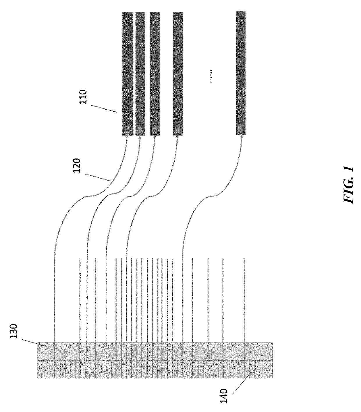
[0040]Lidar is a type of ranging sensor characterized by long detection distance, high resolution, and low interference by the environment. Lidar has been widely applied in the fields of intelligent robots, unmanned aerial vehicles, autonomous driving or self-driving. The working principle of Lidar is estimating a distance based on a round trip time of electromagnetic waves between a source and a target.
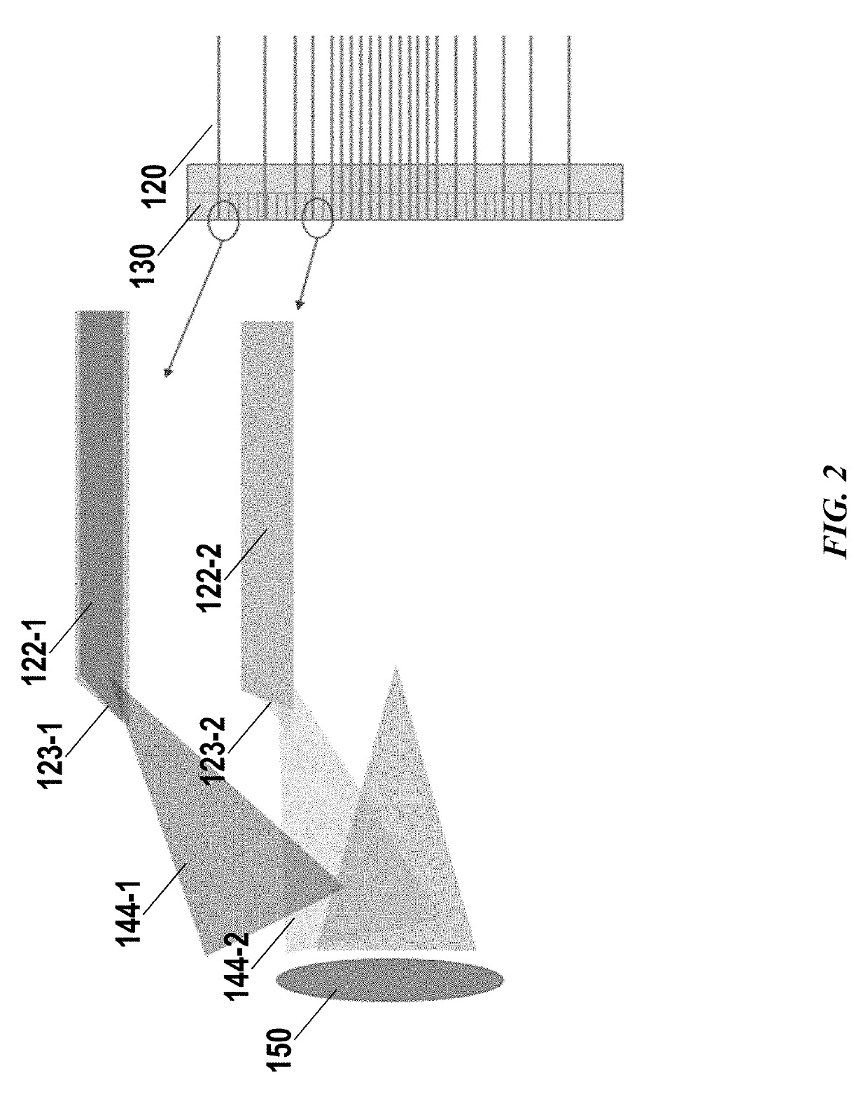
[0041]Multiline Lidar has been increasingly used in research and commercial applications. In a multiline Lidar system,...
PUM
 Abstract
Description
Claims
Application Information