Method of manufacturing a fan blade and a fan blade

a technology of gas turbine engine and fan blade, which is applied in the direction of machines/engines, other domestic objects, mechanical apparatus, etc., can solve the problems of time-consuming and expensive, and the flow of core material may be relatively limited during compression moulding, so as to achieve the effect of relatively limited flow of core material

Active Publication Date: 2019-10-10
ROLLS ROYCE PLC
View PDF0 Cites 3 Cited by
  • Summary
  • Abstract
  • Description
  • Claims
  • Application Information

AI Technical Summary

Benefits of technology

[0013]By providing a relatively high proportion of the core material in the initial application, an amount of flow of the core material may be relatively limited during compression moulding. This may be advantageous in substantially maintaining the fibre orientation distribution (FOD) of the short fibres within the resin, such that the compression forming does not adversely affect the quasi-isotropic nature of the core material.

Problems solved by technology

However, manufacturing such fan blades by known lay-up procedures can be time consuming and expensive.
By providing a relatively high proportion of the core material in the initial application, an amount of flow of the core material may be relatively limited during compression moulding.

Method used


Image

  • Method of manufacturing a fan blade and a fan blade
  • Method of manufacturing a fan blade and a fan blade
  • Method of manufacturing a fan blade and a fan blade

Examples


Embodiment Construction

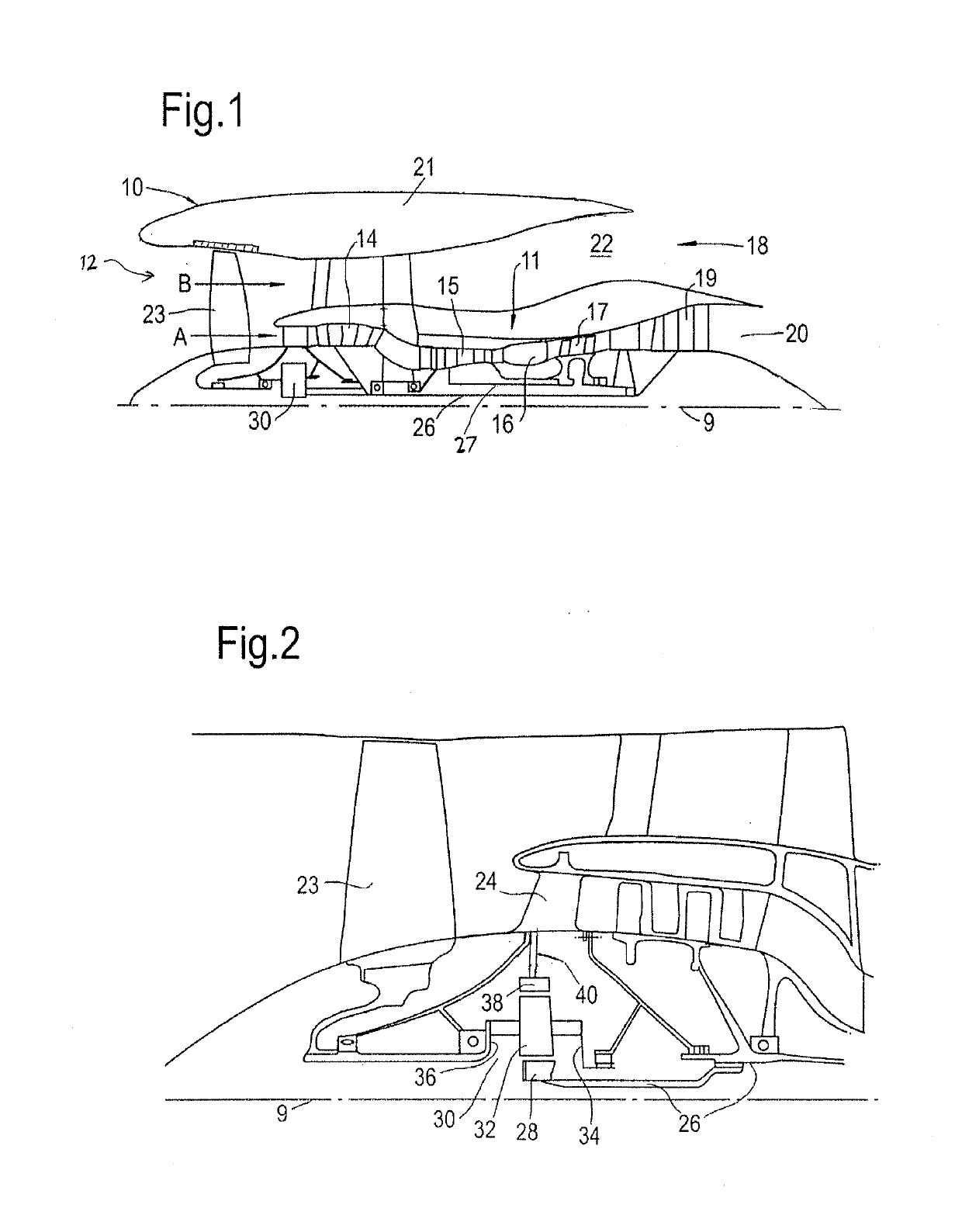
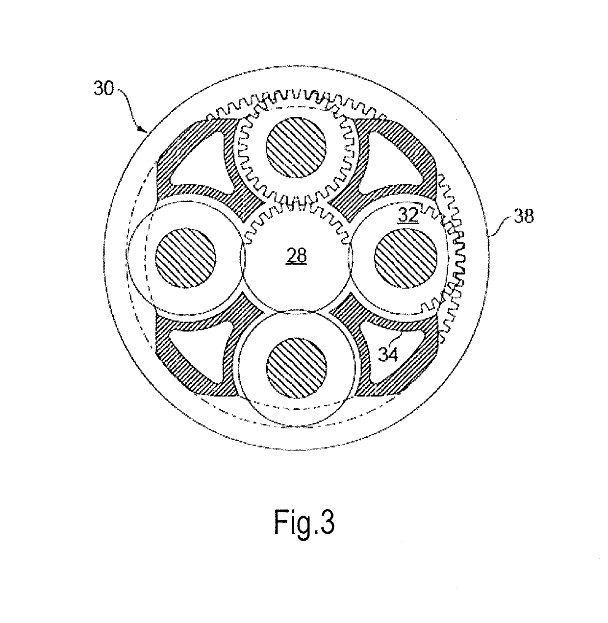
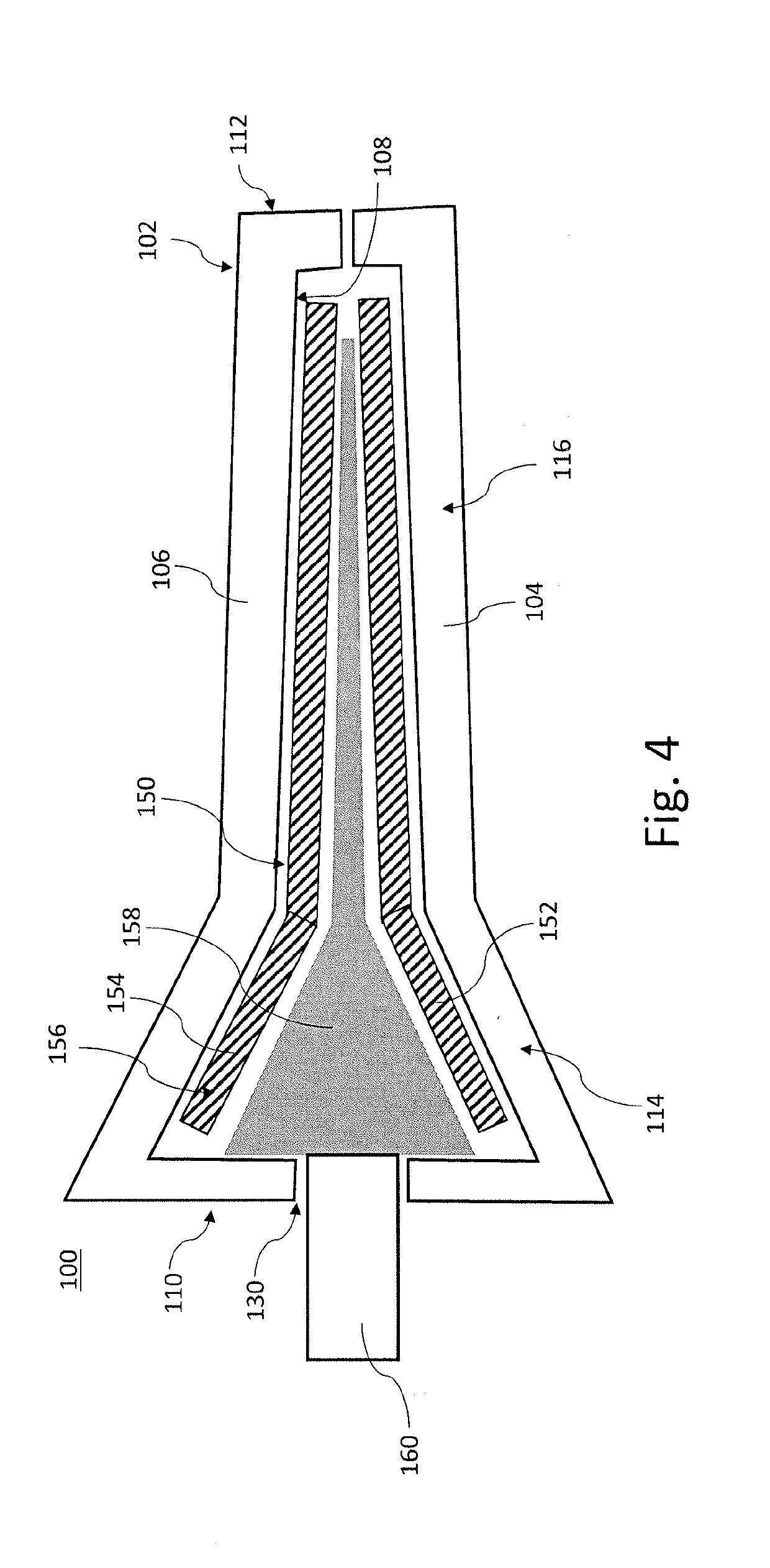
[0058]FIG. 1 illustrates a gas turbine engine 10 having a principal rotational axis 9. The engine 10 comprises an air intake 12 and a propulsive fan 23 that generates two airflows: a core airflow A and a bypass airflow B. The gas turbine engine 10 comprises a core 11 that receives the core airflow A. The engine core 11 comprises, in axial flow series, a low pressure compressor 14, a high-pressure compressor 15, combustion equipment 16, a high-pressure turbine 17, a low pressure turbine 19 and a core exhaust nozzle 20. A nacelle 21 surrounds the gas turbine engine 10 and defines a bypass duct 22 and a bypass exhaust nozzle 18. The bypass airflow B flows through the bypass duct 22. The fan 23 is attached to and driven by the low pressure turbine 19 via a shaft 26 and an epicyclic gearbox 30.

[0059]In use, the core airflow A is accelerated and compressed by the low pressure compressor 14 and directed into the high pressure compressor 15 where further compression takes place. The compres...


PUM

PropertyMeasurementUnit
diameteraaaaaaaaaa
diameteraaaaaaaaaa
diameteraaaaaaaaaa

Abstract

A method of manufacturing a fan blade for a gas turbine engine. The method includes providing a compression mould having an internal mould surface corresponding to an outer profile of a fan blade, providing opposing first and second laminates to form a shell corresponding to the mould surface, each laminate comprising a lay-up of plies of fibre reinforcement material, applying a core material comprising quasi-isotropic short fibre reinforced resin in the compression mould so that with the compression mould in a moulding configuration the core material is enclosed by the shell, the core material and the shell forming a pre-form for the fan blade, applying pressure to compress the pre-form so that it conforms to the mould surface, and applying heat to cure the pre-form.

Description

CROSS-REFERENCE TO RELATED APPLICATIONS[0001]This specification is based upon and claims the benefit of priority from UK Patent Application Number 1803802.6 filed on 9 Mar. 2018, and UK Patent Application Number 1805546.7 filed on 4 Apr. 2018 the entire contents of which are incorporated herein by reference.BACKGROUNDField of the Disclosure[0002]The present disclosure relates to a method of manufacturing a fan blade for a gas turbine engine, and a fan blade of a gas turbine engine.Description of the Related Art[0003]It is known to provide fan blades comprising fibre reinforced composite materials for gas turbine engines. Such composite materials can provide a lightweight and strong fan blade structure. However, manufacturing such fan blades by known lay-up procedures can be time consuming and expensive.SUMMARY[0004]According to a first aspect, there is provided a method of manufacturing a fan blade for a gas turbine engine, the method comprising providing a compression mould having ...

Claims


Application Information

Patent Timeline
Patent Type & Authority Applications(United States)
IPC IPC(8): B29C70/34F01D5/28B29C70/12B29C70/68B29C70/08
CPCB29C70/682B29C70/345B29C70/081B29L2031/08F01D5/282B29C70/12B29D99/0025B29C70/30B29C70/46B29C70/68B29C53/04B29C53/382B29C70/36B29C70/70B29L2031/082B32B1/00B32B5/06B32B5/26B32B38/0012B32B38/1808B32B2250/20B32B2255/02B32B2255/26B32B2305/076B32B2603/00F01D5/147F05D2220/32F05D2300/603F05D2300/611F05D2230/40F05D2300/44F05D2300/6034B29C70/54
Inventor BACKHOUSE, ROBERT C.GILL, VINCENT
Owner ROLLS ROYCE PLC
Why Eureka
Try Eureka