Vehicle and method of charging vehicle

a charging method and vehicle technology, applied in the direction of charging stations, electric propulsion mounting, charging cables, etc., can solve the problems of excessive temperature at the contact portion, limiting the charging power of the charger mounted in the vehicle, and affecting the service life of the vehicle, so as to shorten the charging time and improve the user's convenience. , the effect of shortening the charging tim

Active Publication Date: 2019-10-10
TOYOTA JIDOSHA KK
View PDF0 Cites 12 Cited by
  • Summary
  • Abstract
  • Description
  • Claims
  • Application Information

AI Technical Summary

Benefits of technology

[0005]Plug-in charging causes heat loss (Joule heat) in a portion of contact between the connector provided at the end of the charging cable and the inlet on the vehicle side (hereinafter abbreviated as a “contact portion”), which leads to a particular concern that the temperature at the contact portion may excessively rise. On the other hand, it is also desired to shorten the charging time for improving the user's convenience. The charging time is shortened by increasing the charging power. However, when the charging power (more specifically, the current supplied from a charging facility) is increased, the heat loss occurring in the contact portion is also increased accordingly, which leads to a further concern that the contact portion may be overheated. Thus, it is required to shorten the charging time as much as possible while appropriately protecting the charging cable and the inlet.

Problems solved by technology

Plug-in charging generally causes heat loss in a charging facility, a charging cable, and a charging inlet of a vehicle.
Then, when there is a possibility that the temperature of the power feeding device or the charging cable may exceed the heatproof temperature, the power supply device limits the charging power of the charger mounted in the vehicle.
Plug-in charging causes heat loss (Joule heat) in a portion of contact between the connector provided at the end of the charging cable and the inlet on the vehicle side (hereinafter abbreviated as a “contact portion”), which leads to a particular concern that the temperature at the contact portion may excessively rise.
However, when the charging power (more specifically, the current supplied from a charging facility) is increased, the heat loss occurring in the contact portion is also increased accordingly, which leads to a further concern that the contact portion may be overheated.
Assuming that the same charging mode is set for the power storage device irrespective of whether the charging facility is provided with a cooling mechanism or not, and when the charging mode is set based on the charging facility not provided with a cooling mechanism, the charging power from the charging facility provided with a cooling mechanism is small, which may prevent the charging time from being sufficiently shortened.
On the other hand, when the charging mode is set based on the charging facility provided with a cooling mechanism, the charging power from the charging facility not provided with a cooling mechanism is excessively increased, which may prevent sufficient protection of the charging facility.

Method used


Image

  • Vehicle and method of charging vehicle
  • Vehicle and method of charging vehicle
  • Vehicle and method of charging vehicle

Examples


first embodiment

[0031]

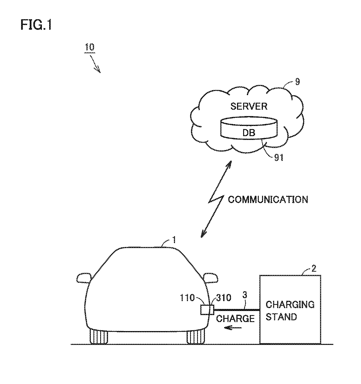
[0032]FIG. 1 is a diagram schematically showing the entire configuration of a charging system according to the first embodiment of the present disclosure. Referring to FIG. 1, a charging system 10 includes a vehicle 1, a charging stand 2, a charging cable 3, and a server 9.

[0033]Vehicle 1 and charging stand 2 are configured to be electrically connectable to each other through charging cable 3. Vehicle 1 is a user's (not shown) vehicle, and may be a plug-in hybrid vehicle, for example. Vehicle 1 may be an electric vehicle as long as it is configured to allow plug-in charging.

[0034]FIG. 1 shows the state where plug-in charging is performed for vehicle 1 by charging stand 2. Charging stand 2 is a public charging stand (or a charging station), for example. Thus, plug-in charging by charging stand 2 may be performed for a vehicle (not shown) other than vehicle 1. Furthermore, plug-in charging for vehicle 1 may be performed by a charging stand (not shown) other than charging stand 2...

second embodiment

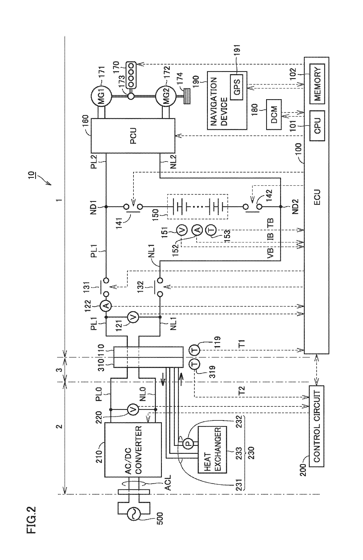
[0089]The first embodiment has been described with regard to an example of the configuration in which the position of the target charging stand is specified using the GPS information of vehicle 1 and the maximum allowable current is switched based on the positional information about the charging stand. However, it is not indispensable to use the positional information about the target charging stand for specifying the target charging stand. The second embodiment will be described with regard to the configuration in which the maximum allowable current is set through the communication between vehicle 1 and the target charging stand. In the second embodiment, a charging table TBL2 different from charging table TBL1 is stored in memory 102 of ECU 100. The configurations of the target charging stand and the vehicle in the second embodiment other than the configurations described above are basically the same as those shown in FIG. 2, and therefore, the description thereof will not be repe...


PUM


Abstract

A vehicle is configured to perform plug-in charging for charging a battery mounted in the vehicle with electric power supplied through a charging cable from a charging stand. The vehicle includes: an inlet to which a connector of the charging cable is connectable; and an ECU configured to control a supply current from the charging stand such that the supply current does not exceed a maximum allowable current. The ECU is configured to obtain specific information as to whether or not the charging stand is provided with a cooling mechanism for cooling the connector and the inlet. The ECU is configured to set the maximum allowable current to be higher when the charging stand is provided with the cooling mechanism than when the charging stand is not provided with the cooling mechanism.

Description

[0001]This nonprovisional application is based on Japanese Patent Application No. 2018-073640 filed on Apr. 6, 2018 with the Japan Patent Office, the entire contents of which are hereby incorporated by reference.BACKGROUNDField[0002]The present disclosure relates to a vehicle and a method of charging the vehicle, and more particularly to a technique for charging a power storage device mounted in a vehicle with electric power supplied through a charging cable from a charging facility external to the vehicle.Description of the Background Art[0003]In recent years, there has been advancement of developing an electrically powered vehicle configured to allow “plug-in charging” for charging a power storage device mounted in a vehicle with electric power supplied through a charging cable from a charging facility (a charging stand and the like) external to the vehicle. Plug-in charging generally causes heat loss in a charging facility, a charging cable, and a charging inlet of a vehicle. Acc...

Claims


Application Information

Patent Timeline
Patent Type & Authority Applications(United States)
IPC IPC(8): B60L53/302B60K1/04B60L53/30B60L53/36B60L53/65B60L53/16
CPCB60L53/16B60L53/36B60L53/302B60L53/65B60L53/305B60L2240/10B60K1/04B60L53/14B60L53/66B60L53/62Y02T10/70Y02T10/7072
Inventor TSUKAMOTO, SHOTA
Owner TOYOTA JIDOSHA KK
Why Eureka
Try Eureka