
Eureka
For R&D, Eureka makes reading and utilizing patents & technical documents easy.
Eureka AIR
Designed for self-driven R&D workflows. Generate viable solutions, solve complex R&D challenges, empower your innovation with AI.

Eureka Materials
Designed for material experts only. Revolutionize your material R&D, from search, analyze, to developing new materials.

TechResearch
Generate reliable direction feasibility study reports for your R&D in just a few steps.

TechSeek
Discover and master advanced knowledge NOW. Basics, ideas, possibilities, all at once.

TechMind
As an expert in R&D Theories, TechMind can generates customized viable solutions instantly.

TechRisk
Analyze your overall solution with one click, know your potential R&D risks in advance.

TechMonitor
Get weekly tech updates, stay abreast of the latest tech innovations and key insights.
Mirror drive device and image pickup apparatus using this
- Summary
- Abstract
- Description
- Claims
- Application Information
AI Technical Summary
Benefits of technology
Problems solved by technology
Method used
Image

Examples
first embodiment
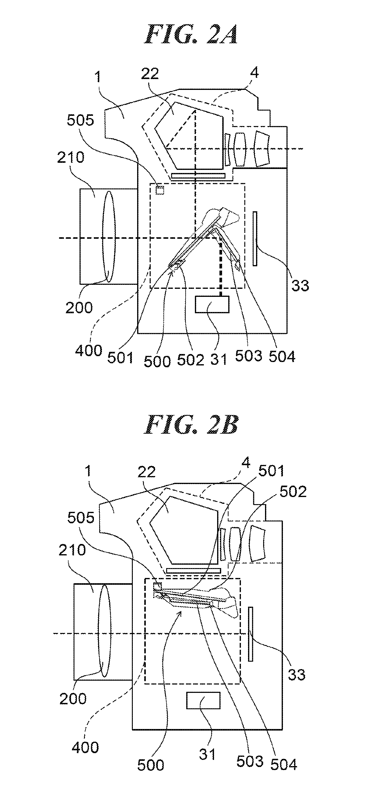
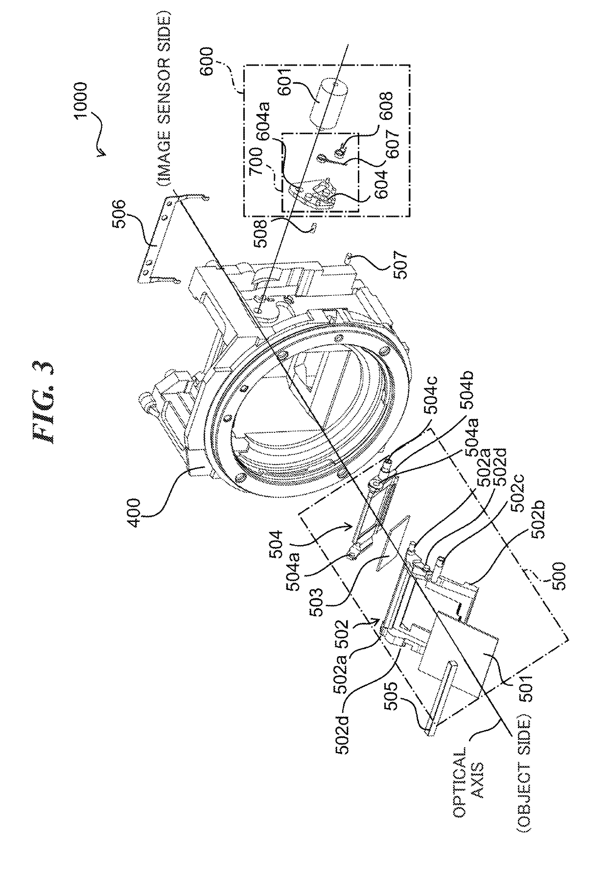
[0039]Next, the present invention will be described. FIG. 2A is a schematic sectional view of the image pickup apparatus in a case where the main mirror 501 and the sub mirror 503 are in the mirror-down state. FIG. 2B is a schematic sectional view of the image pickup apparatus in a case where the main mirror 501 and the sub mirror 503 are in the mirror-up state. The main mirror 501 is held by a main-mirror holder 502, and the sub mirror 503 is held by a sub-mirror holder 504. The main-mirror holder 502 is rotatably supported by a mirror box 400 (see FIG. 3), and the sub-mirror holder 504 is supported so as to be rotatable with respect to the main-mirror holder 502.
[0040]In the following description, the main-mirror holder 502 shall always hold the main mirror 501, and the sub-inirror holder 504 shall always hold the sub mirror 503. Accordingly, the position of the main mirror 501 is indicated by the position of the main-mirror holder 502, and the position of the sub mirror 503 is in...
second embodiment
[0079]FIG. 9A is a view showirw a condition where the mirror drive unit is in the mirror-down state as with FIG. 5. In this condition, the one end 607a of the spring 607 is locked by the first spring-locking part 604d of the drive lever 604 and the other end 607b energizes the drive dowel 502c of the main-mirror holder 502 in the mirror-down direction. Thereby, the down-position contact part 502b of the main-mirror holder 502 contacts the positioning dowel 507. At this time, the main-mirror drive part 604b of the drive lever 604 is not in contact with the drive dowel 502c.
[0080]The main-mirror drive part 604b of the drive lever 604 has a first area 604b-1 that faces the drive dowel 502c of the main-mirror holder 502 in the case where the drive lever 604 is located at the down-holding position. A mirror-dowm side and mirror-up side of the first area 604b-1 are approximately parallel to a straight line that connects the center of the rotating shaft 502a of the main-mirror holder 502...
third embodiment
[0090]As described above, when the mirror drive unit is in the mirror-down state, the sub-mirror drive part 604c of the drive lever 604 contacts the drive dowel 504c of the sub-mirror holder 504 in the Accordingly, the width of the sub-mirror drive part 604c can be narrowed. This enables reduction of the generation of the mirror-down bound because the speed of the sub-mirror holder 504 just before reaching the mirror-down state during the mirror-down action is controlled by the shape of the sub-mirror drive part 604c.
[0091]Next, a fourth embodiment of the present invention will be described. Among components of the mirror device according to the fourth embodiment, equivalent parts and parts having, equivalent functions to the components of the mirror drive device 1000 according to the first embodiment shall be indicated by the same reference numerals in FIG. 11 referred. Descriptions about the mirror drive device according to the fog ith embodiment that are common to that of the m...
PUM
 Abstract
Description
Claims
Application Information
 - R&D Engineer
- R&D Manager
- IP Professional
- Industry Leading Data Capabilities
- Powerful AI technology
- Patent DNA Extraction
Browse by: Latest US Patents, China's latest patents, Technical Efficacy Thesaurus, Application Domain, Technology Topic, Popular Technical Reports.
© 2024 PatSnap. All rights reserved.Legal|Privacy policy|Modern Slavery Act Transparency Statement|Sitemap|About US| Contact US: help@patsnap.com