Antenna apparatus

a technology of antenna elements and antennas, applied in the field of antenna apparatuses, can solve the problems of deterioration of various antenna characteristics, such as the side lobe ratio and the antenna gain itself, and the insufficient supply of signals from the line to the radiating element, so as to achieve the effect of reducing the length of the antenna element in the extending direction

Active Publication Date: 2019-10-10
DENSO TEN LTD
View PDF0 Cites 4 Cited by
  • Summary
  • Abstract
  • Description
  • Claims
  • Application Information

AI Technical Summary

Benefits of technology

[0007]Thus, a length of an antenna element in an extending direction can be shortened, so that an antenna apparatus can be downsized.

Problems solved by technology

However, in the conventional technology, there has been a problem that signals are not sufficiently supplied from the line to the radiating element (or the radiating element to the line).
For example, when electric power is not sufficiently supplied to the radiating element, a beam pattern of a radar apparatus, or the like, collapses, so that various antenna characteristics, such as a side lobe ratio and an antenna gain itself, may deteriorate.

Method used


Image

  • Antenna apparatus
  • Antenna apparatus
  • Antenna apparatus

Examples


Embodiment Construction

[0027]An embodiment of an antenna apparatus disclosed in the application will be hereinafter described in detail with reference to accompanying drawings. The invention is not limited to the embodiment. A case in which the antenna apparatus is a transmitting antenna that radiates radio waves outside will be hereinafter described, as an example, but the antenna apparatus may be a receiving antenna that receives radio waves.

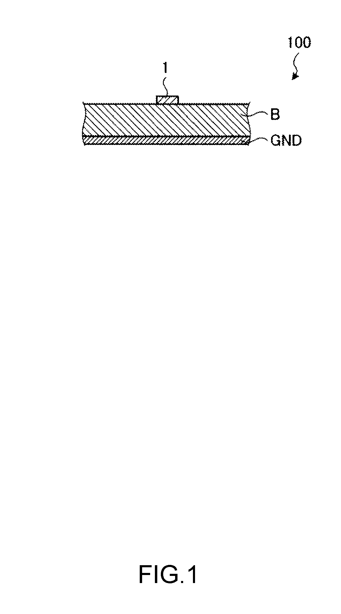
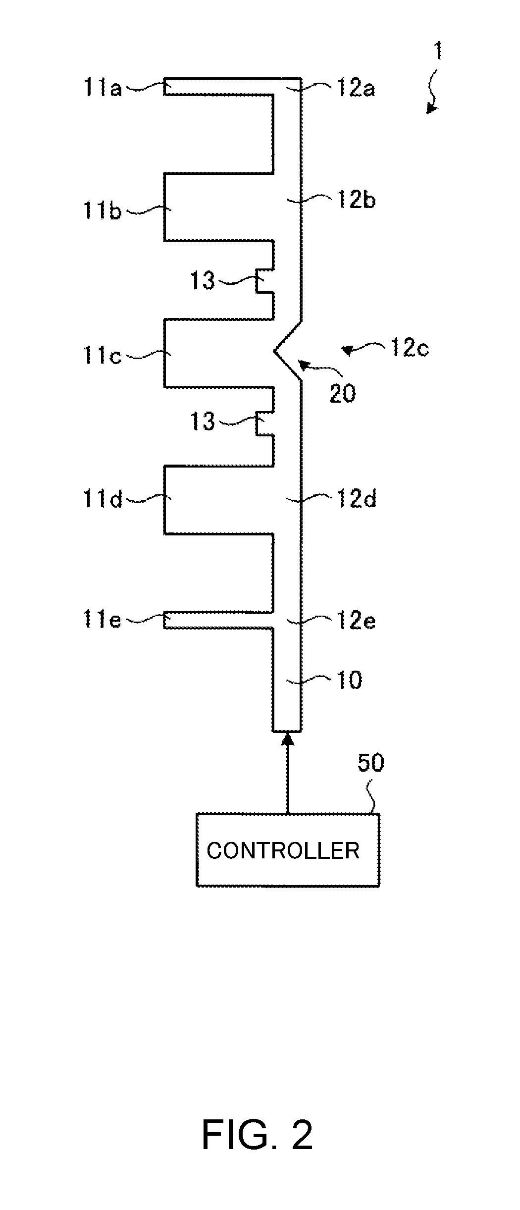
[0028]First, description will be made on an outline of the antenna apparatus according to the embodiment with reference to FIG. 1 and FIG. 2. FIG. 1 illustrates a cross-sectional view of the antenna apparatus according to the embodiment. FIG. 2 illustrates a front view of an antenna element according to the embodiment. FIG. 2 illustrates a standing-wave excitation-type antenna element.

[0029]An antenna apparatus 100 is mounted on a radar apparatus that detects a target by transmitting and receiving radio waves having, for example, a Frequency Modulated Continuous Wav...


PUM


Abstract

An antenna apparatus according to an embodiment includes a linear feed line and a radiating element that protrudes laterally from a first side of the feed line. The radiating element is formed by a conductive pattern, and an opening pattern is located in a portion of the feed line from which the radiating element protrudes. The opening pattern extends into a portion of the radiating element.

Description

BACKGROUND OF THE INVENTIONField of the Invention[0001]The invention relates to an antenna apparatus.Description of the Background Art[0002]Conventionally, there has been an antenna apparatus that transmits and receives radio waves in a millimeter wave band and a microwave band. Such an antenna apparatus has been widely used, for example, in an on-vehicle radar apparatus, and the like. As for the antenna apparatus, a technology of connecting a line formed on a dielectric substrate, through which signals propagate, to a radiating element for transmitting and receiving radio waves has been known.[0003]However, in the conventional technology, there has been a problem that signals are not sufficiently supplied from the line to the radiating element (or the radiating element to the line). For example, when electric power is not sufficiently supplied to the radiating element, a beam pattern of a radar apparatus, or the like, collapses, so that various antenna characteristics, such as a si...

Claims


Application Information

Patent Timeline
Patent Type & Authority Applications(United States)
IPC IPC(8): H01Q21/00H01Q1/38G01S7/03
CPCH01Q21/0037G01S7/032H01Q1/38G01S13/931G01S7/03H01Q21/08
Inventor YOSHITAKE, HIROAKINISHIMOTO, NORIHISA
Owner DENSO TEN LTD
Why Eureka
Try Eureka