RFID tag with antenna comprising optical code or symbol

a technology of optical code or symbol and antenna, which is applied in the field of antenna for an rfid transponder or tag, can solve the problems that prior art rfid devices may also lack distinctive and attractive looks, subject to certain limitations, etc., and achieve the effect of reducing the effective axial length of the antenna, reducing the resonant frequency of the antenna, and facilitating correction

Inactive Publication Date: 2006-10-19
INTERMEC IP
View PDF1 Cites 43 Cited by
  • Summary
  • Abstract
  • Description
  • Claims
  • Application Information

AI Technical Summary

Benefits of technology

[0015] In the foregoing embodiment, folds in the interconnected letters of text may comprise either a uniform or non-uniform meander line antenna element, depending on a selected text font and placement of the conductive traces connecting the letters of text. Folds along the length of the antenna trace may reduce the resonant frequency of the antenna, compared with a straight dipole antenna of the same axial length. This reduction in resonant frequency may be proportional to the total wire length. Thus, using interconnected text as the antenna element may reduce the effective axial length of the antenna by a predictable degree, which may be readily corrected for when configuring an antenna to convey different alpha-numeric or other human-readable information.

Problems solved by technology

Notwithstanding the advantages of such optical labels, they are subject to certain limitations.
Prior art RFID devices may also lack a distinctive and attractive look, which would be beneficial for applications such as consumer packaging or for brand promotion.

Method used


Image

  • RFID tag with antenna comprising optical code or symbol
  • RFID tag with antenna comprising optical code or symbol
  • RFID tag with antenna comprising optical code or symbol

Examples


Embodiment Construction

[0023] The present invention provides an RFID tag with an antenna comprising an optical code or symbol, for example, a machine-readable bar code or human-readable text. In the detailed description that follows, like element numerals will be used to indicate like elements appearing in one or more of the figures.

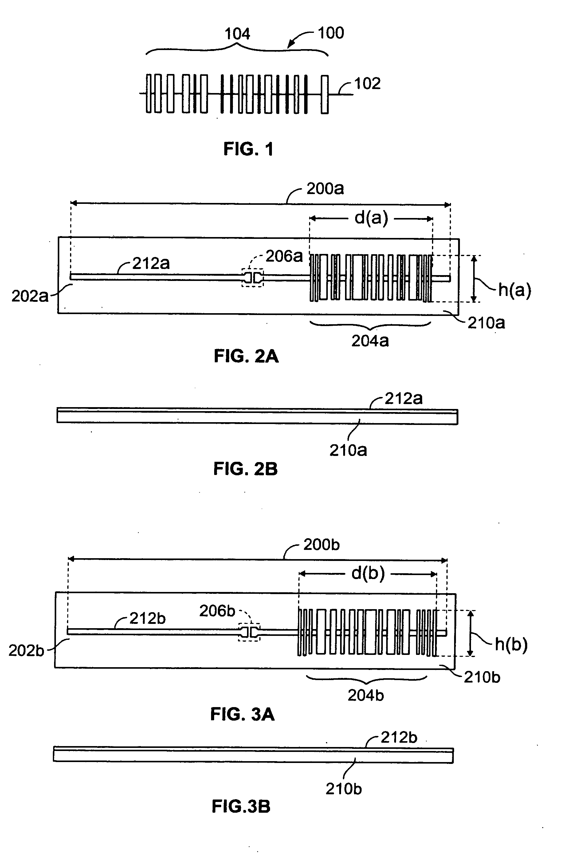
[0024]FIG. 1 is a diagram showing an RFID tag antenna 100 configured as a machine-readable code in accordance with an embodiment of the present invention. In RFID antenna 100, horizontal line 102 denotes a transverse conductive trace and a series of vertical lines 104 connected by trace 102 are configured as an optical bar code. The length of the horizontal trace 102 determines the tag resonant frequency and the antenna gain. The series of vertical traces 104 may improve antenna bandwidth, but different vertical arrangements, so long as occupying the same area, should not appreciably change the antenna resonant frequency or gain of the illustrated design. For example, the spa...


PUM


Abstract

A radio frequency identification (RFID) tag includes an antenna having a shape providing a machine-readable or human-readable code or symbol. For example, a machine-readable code may comprise a bar code, or other suitable optical code. Human-readable symbols may include, for example, text, alpha-numeric symbols, icons, or pictographs. Using human-readable antenna forms, an RFID tag may be used as a label, for example, to add a distinctive look to the tagged product, to further identify the tag or product it is attached to, or for branding the tag or attached product.

Description

RELATED APPLICATION DATA [0001] This patent application claims priority pursuant to 35 U.S.C. § 119(e) to provisional patent application Ser. No. 60 / 671,211, filed Apr. 13, 2005, the subject matter of which is incorporated herein in its entirety.BACKGROUND OF THE INVENTION [0002] 1. Field of the Invention [0003] The present invention relates to radio frequency identification (RFID) systems and more particularly, to an antenna for an RFID transponder or tag. [0004] 2. Description of Related Art [0005] Radio frequency identification technology is a wireless technology for data transfer used in many different applications, such as electronic toll collection, railway car identification and tracking, intermodal container identification, asset identification, tracking and item management for retail, health care and logistics applications. An RFID system includes one or more transponders, i.e., tags, comprised of a semiconductor chip and an antenna, and one or more read / write devices, also...

Claims


Application Information

Patent Timeline
Patent Type & Authority Applications(United States)
IPC IPC(8): G08B13/14
CPCG06K19/07749G06K19/06018
Inventor LAM, FOR SANDERKODUKULA, VENKATA S.NIKITIN, PAVEL V.PILLAI, VIJAY
Owner INTERMEC IP
Why Eureka
Try Eureka