Uplink signaling of direct current (DC) tone location in new radio (NR)

Active Publication Date: 2019-10-10
QUALCOMM INC
View PDF0 Cites 12 Cited by
  • Summary
  • Abstract
  • Description
  • Claims
  • Application Information

AI Technical Summary

Benefits of technology

[0009]Embodiments of the present disclosure provide mechanisms for efficient reporting of direct current (DC) locations. For example, a user equipment (UE) may report DC location information related to the UE's receiver and/or the UE's transmitter based on certain events, such as a carrier aggregation (CA) reconfiguration command, a bandwidth part (BWP) switch command, and/or a BWP reconfiguration command received from a base station (BS). The UE may report DC locations per BWP and p

Problems solved by technology

While the use of higher frequencies (e.g., above 6 GHz) can provide a greater transmission capacity, phase noise levels may increase with the higher frequencies.
Phase noise can impact the performance of certain wireless communication systems.
Depending on the location of a reference signal within radio frequency (RF) resources, however, a receiver may be unable to e

Method used


Image

  • Uplink signaling of direct current (DC) tone location in new radio (NR)
  • Uplink signaling of direct current (DC) tone location in new radio (NR)
  • Uplink signaling of direct current (DC) tone location in new radio (NR)

Examples


Example

[0034]The detailed description set forth below, in connection with the appended drawings, is intended as a description of various configurations and is not intended to represent the only configurations in which the concepts described herein may be practiced. The detailed description includes specific details for the purpose of providing a thorough understanding of the various concepts. However, it will be apparent to those skilled in the art that these concepts may be practiced without these specific details. In some instances, well-known structures and components are shown in block diagram form in order to avoid obscuring such concepts.

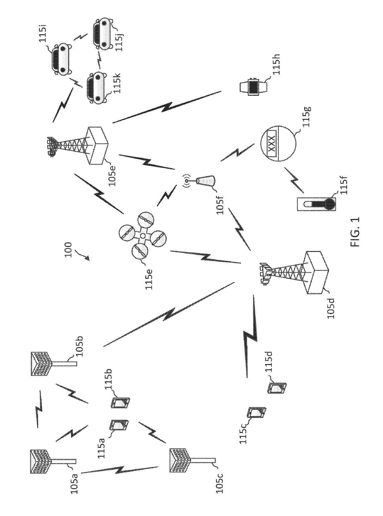
[0035]This disclosure relates generally to wireless communications systems, also referred to as wireless communications networks. In various embodiments, the techniques and apparatus may be used for wireless communication networks such as code division multiple access (CDMA) networks, time division multiple access (TDMA) networks, frequency division ...


PUM


Abstract

Wireless communications systems and methods related to signaling of direct current (DC) locations of user equipment devices (UEs) in a new radio (NR) network are provided. A wireless communication device receives, from a base station, at least one of a carrier aggregation (CA) configuration or a bandwidth part (BWP) configuration. The wireless communication device determines a direct current (DC) location based on at least one of the CA configuration or the BWP configuration. The wireless communication device transmits, to the base station, a report based on the determined DC location. The wireless communication device communicates, with the base station, a phase tracking reference signal (PTRS) configured based on the report.

Description

CROSS REFERENCE TO RELATED APPLICATIONS[0001]The present application claims priority to and the benefit of the U.S. Provisional Patent Application No. 62 / 680,225, filed Jun. 4, 2018, U.S. Provisional Patent Application No. 62 / 660,164, filed Apr. 19, 2018, and U.S. Provisional Patent Application No. 62 / 655,797, filed Apr. 10, 2018, each of which is hereby incorporated by reference in its entirety as if fully set forth below and for all applicable purposes.TECHNICAL FIELD[0002]This application relates to wireless communication systems, and more particularly to signaling of direct current (DC) locations of user equipment devices (UEs) in a new radio (NR) network. Certain embodiments can enable and provide solutions and techniques for UEs to efficiently report DC locations to improve reference signal (e.g., phase tracking reference signals (PTRSs)) communication.INTRODUCTION[0003]Wireless communications systems are widely deployed to provide various types of communication content such a...

Claims


Application Information

Patent Timeline
IPC IPC(8): H04W72/04
CPCH04W72/0406H04L5/001H04L5/0048H04L5/0053H04L5/0092H04W72/0453H04W56/0035H04W72/21H04W72/20
Inventor KUBOTA, KEIICHILUO, TAOMANOLAKOS, ALEXANDROSNAM, WOOSEOKVERMA, SUMITGAAL, PETER
Owner QUALCOMM INC
Why Eureka
Try Eureka