Time and frequency synchronization for spread radar systems

a spread radar and time and frequency synchronization technology, applied in the direction of using reradiation, measuring devices, instruments, etc., can solve the problems of synchronization of antennas on the scale of a period of radar carrier frequency, ambiguity in angular reconstruction, etc., to achieve fast modification of method steps and robust and reliable execution of methods

Active Publication Date: 2019-10-17
IEE INT ELECTRONICS & ENG SA
View PDF0 Cites 9 Cited by
  • Summary
  • Abstract
  • Description
  • Claims
  • Application Information

AI Technical Summary

Benefits of technology

[0049]The software module can enable a robust and reliable execution of the method and can allow for a fast modification of method steps if appropriate.

Problems solved by technology

A displacement of the antennas by multiple wavelengths leads to ambiguity in angular reconstruction.
In such systems with multiple antennas spread out over the face of a car, wherein a distance between the antennas is large compared to the radar carrier wavelength, a synchronization of the antennas on the scale of a period of the radar carrier frequency represents an issue because the standard CAN-bus from the 1980s is capable of ensuring a latency only up to 120 μs for high priority messages.

Method used


Image

  • Time and frequency synchronization for spread radar systems
  • Time and frequency synchronization for spread radar systems
  • Time and frequency synchronization for spread radar systems

Examples


Embodiment Construction

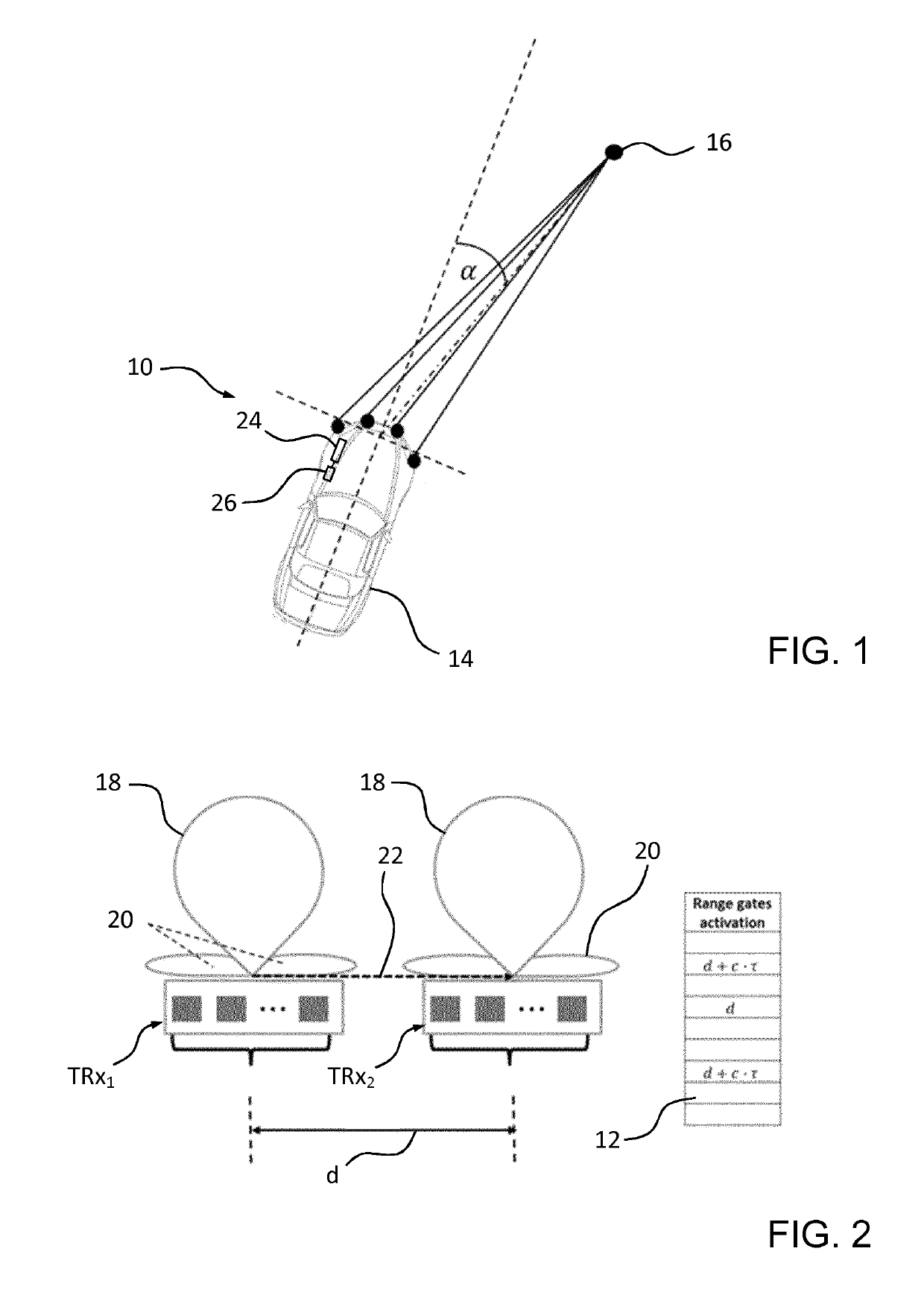
[0059]FIG. 1 shows a possible embodiment of an automotive spread radar system 10 in accordance with the invention. The automotive spread radar system 10 is configured for detecting reflecting targets 16 in its field of view, for unambiguously measuring a range to and a relative radial velocity of each of the detected targets 16, and for measuring an angle of arrival a of the reflected radar signal of each of the detected targets 16.

[0060]Means and methods to determine the above-mentioned quantities from radar signals received after having been reflected by a target 16 in the field of view of the radar system are well known in the art, for instance in the prior art cited herein, and shall therefore not be described in detail herein.

[0061]The automotive spread radar system 10 is installed in a vehicle 14 formed by a passenger car to provide information that is to be used as an input for a collision avoidance system of the vehicle 14. The automotive spread radar system 10 comprises a p...


PUM


Abstract

An automotive spread MIMO-configured radar system has a plurality of transceiver antenna units for transmitting mutually orthogonal radar waves. Each transceiver antenna unit has a plurality of range gates to indicate a range detected by the transceiver antenna unit. At least one specific transceiver antenna unit (TRx1) is configured to transmit a reference signal received directly by at least one transceiver antenna unit (TRx2) that is separated by an a priori known distance from the specific transceiver antenna unit (TRx1). An evaluation and control unit is configured for reading out the plurality of range gates for the transceiver antenna unit (TRx2), and, based on the read-out range gate that indicates the received reference signal and based on the a priori known distance, for synchronizing the specific transceiver antenna unit (TRx1) and the transceiver antenna unit (TRx2) that received the reference signal and/or for correcting a measured Doppler shift.

Description

TECHNICAL FIELD[0001]The invention relates to an automotive spread multiple-input multiple-output configured radar system for detection of targets, and / or for measuring relative velocity of detected targets and / or for measuring an angle of arrival of a radar signal reflected by a target, to a method of operating such automotive spread multiple-input multiple-output configured radar system, and to a software module for controlling automatic execution of steps of such method.BACKGROUND OF THE INVENTION[0002]It is known in the art to employ radar technology, in particular in the millimeter wave range between 75 and 81 GHz, in exterior automotive applications such as driver assistance systems for providing improved safety by facilitating an optimized reaction of a driver of a vehicle with appropriate warnings or even by automatically taking over control of the vehicle, for instance in collision avoidance systems.[0003]It is further known to employ a multiple-input multiple-output (MIMO)...

Claims


Application Information

Patent Timeline
Patent Type & Authority Applications(United States)
IPC IPC(8): G01S13/87G01S13/32G01S13/34G01S7/40G01S7/02G01S13/93H04B7/0413G01S13/931
CPCG01S2013/9357G01S13/878G01S13/325G01S13/931G01S7/023G01S7/4004G01S2013/9375G01S13/34H04B7/0413G01S7/40G01S13/003G01S2013/93271G01S7/0233G01S7/0234G01S2013/9322
Inventor SCHRODER, UDOBEISE, HANS-PETERSTIFTER, THOMAS
Owner IEE INT ELECTRONICS & ENG SA
Why Eureka
Try Eureka