
Metal mesh touch display structure and manufacturing method thereof

a technology of touch display and metal mesh, applied in the field of display, can solve the problems of higher technical complexity, achieve the effects of avoiding bad circuits, ensuring accuracy, and ensuring accuracy

Inactive Publication Date: 2019-10-17
WUHAN CHINA STAR OPTOELECTRONICS SEMICON DISPLAY TECH CO LTD
View PDF6 Cites 5 Cited by
  • Summary
  • Abstract
  • Description
  • Claims
  • Application Information

AI Technical Summary

Benefits of technology

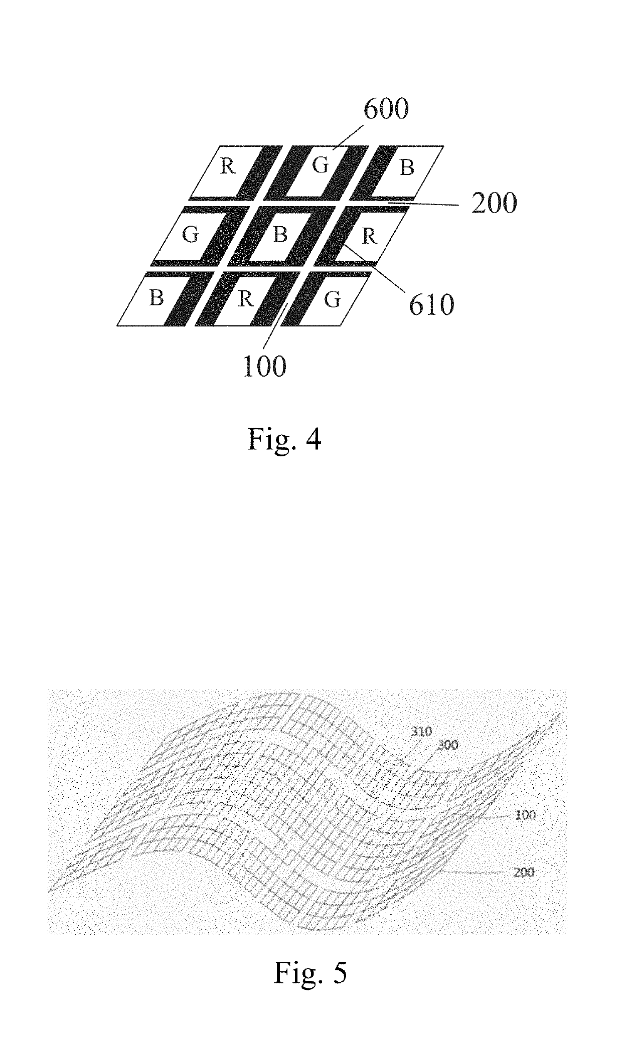
The present invention is a metal mesh touch display structure and its manufacturing method. The technical effect of this patent is that it provides more options for materials to be used as touch wires, resulting in more precise and sensitive touch. The metal mesh wire is hidden between sub-pixels, higher touch resolution can be achieved. The double-layer circuit design reduces the impact on the display aperture ratio, and the many contact points can effectively avoid bad circuit and generate high yield. The metal mesh touch display structure can be used in both LCD and OLED processes and for both hard and flexible products.

Problems solved by technology

Especially in the field of mobile phones requiring higher precision, the technical complexity is higher because of the need to mount a touch device.

Method used


Image

  • Metal mesh touch display structure and manufacturing method thereof
  • Metal mesh touch display structure and manufacturing method thereof
  • Metal mesh touch display structure and manufacturing method thereof

Examples


Embodiment Construction

[0029]To further explain the technical means and effect of the present invention, the following refers to embodiments and drawings for detailed description.

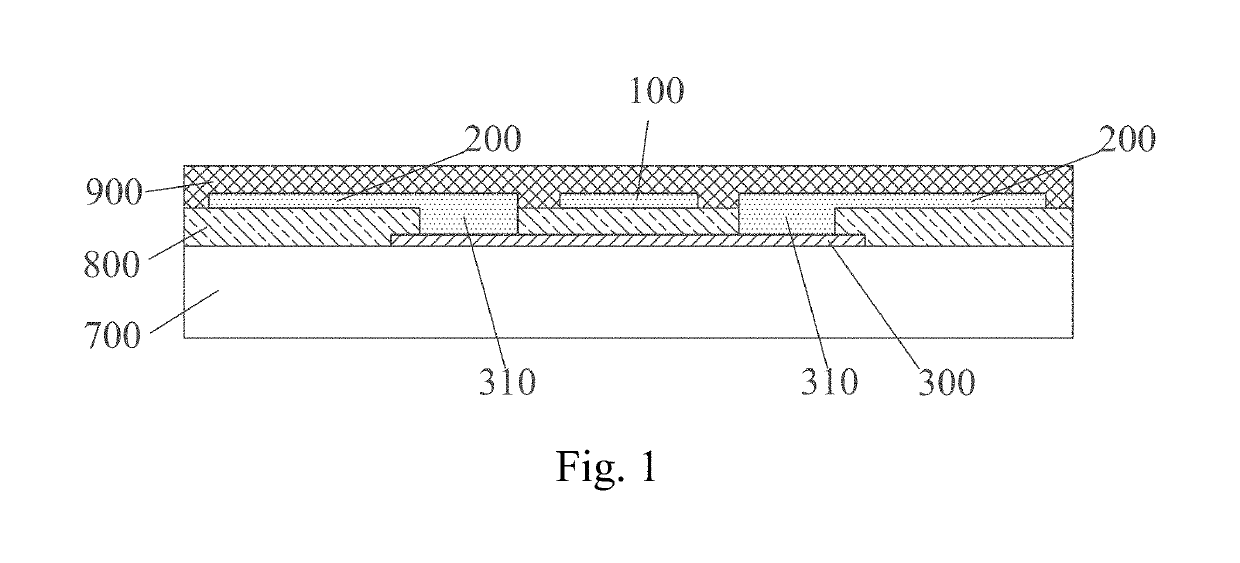
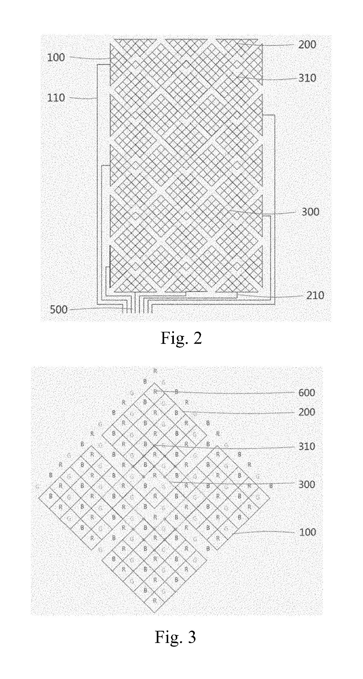
[0030]FIG. 1 is a cross-sectional view showing the metal mesh touch display structure of a preferred embodiment of the present invention. The present invention discloses a metal mesh touch display structure, and the structure integrates the touch function and the display function in a monolithic structure and is widely applicable to display panels. The metal mesh touch display structure comprises: a display device 700 and a metal mesh structure disposed on the display device 700; the metal mesh structure comprises a bridge point 300 disposed on the display device 700, a first protective layer 800 disposed on the bridge point 300, a first metal wire 100 disposed on the first protective layer 800 for forming a first direction electrode of mutual capacitance and a second metal wire 200 for forming a second direction electrode of the...


PUM

PropertyMeasurementUnit
mutual capacitanceaaaaaaaaaa
sizeaaaaaaaaaa
widthaaaaaaaaaa

Abstract

The invention provides a metal mesh touch display structure. The metal mesh touch display structure includes: a display device and a metal mesh structure; the metal mesh structure includes a bridge point, a first protective layer, first and second metal wires, and a second protection layer; the first and second metal wires are mutually insulated, the first metal wire forms a grid pattern corresponding to the shape of the first direction electrode of mutual capacitance, the second metal wire forms a grid pattern corresponding to the shape of the second direction electrode of mutual capacitance The first protective layer is provided with a via corresponding to the bridge point, and the second metal wire is connected to the bridge point through the via; the grid of the grid pattern is formed on light-shielding layer between the pixels of the display device. The invention also provides a corresponding manufacturing method.

Description

BACKGROUND OF THE INVENTION1. Field of the Invention[0001]The present invention relates to the field of display, and in particular to a metal mesh touch display structure and manufacturing method thereof.2. The Related Arts[0002]With the development of technology, display technology has become more diversified, and the battle between organic light-emitting diode (OLED) and liquid crystal display (LCD) also represents fierce competition in various technical schools. Especially in the field of mobile phones requiring higher precision, the technical complexity is higher because of the need to mount a touch device. In the current state of the art, because LCD generally requires liquid crystal (LC) to control light, the LCD usually uses hard screen. The OLED, no longer using LC, can be used on flexible substrates as well as hard substrates. Therefore, the OLED is generally considered as the trend of future developments.[0003]Touch technology as a display assistive technology, especially ...

Claims


Application Information

Patent Timeline
Patent Type & Authority Applications(United States)
IPC IPC(8): G06F3/041G06F3/044G06F3/047
CPCG06F2203/04102G06F2203/04112G06F3/044G06F2203/04103G06F3/047G06F2203/04111H01L27/323G02F1/13338G06F3/0412G06F3/0443G06F3/0446H10K59/40
Inventor FENG, XIAOLIANGLEE, JEONGWOO
Owner WUHAN CHINA STAR OPTOELECTRONICS SEMICON DISPLAY TECH CO LTD
Learn More