Waveform display device

a display device and waveform technology, applied in the field of waveform display devices, can solve the problems of difficult for an inexperienced worker to understand, and the work is difficult for him/her, and achieve the effect of efficiently analysing the waveform of the physical quantity and facilitating the investigation of corresponden

Active Publication Date: 2019-10-17
FANUC LTD
View PDF4 Cites 3 Cited by
  • Summary
  • Abstract
  • Description
  • Claims
  • Application Information

AI Technical Summary

Benefits of technology

[0008]According to the present invention, a worker can easily ascertain the correspondence between a physi

Problems solved by technology

Moreover, when the worker performs the association work, it is difficult for him/her to understand, from waveform data on the spindle positions and speeds and feed axis positions and speed

Method used


Image

  • Waveform display device
  • Waveform display device
  • Waveform display device

Examples


Embodiment Construction

[0017]An embodiment of the present invention will now be described with reference to the accompanying drawings.

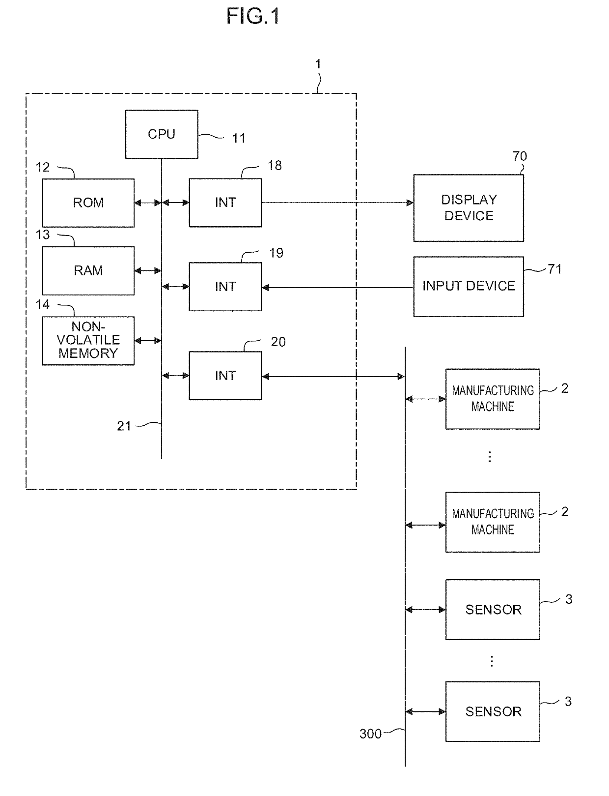
[0018]FIG. 1 is a schematic hardware configuration diagram showing a waveform display device according to one embodiment of the present invention. A waveform display device 1 of the present embodiment is mounted on a control device for controlling manufacturing machines. Moreover, the waveform display device 1 may be mounted on a personal computer adjoined to the control device for controlling the manufacturing machines or a computer, such as a cell computer, host computer, or cloud server, connected to the control device through a network. FIG. 1 shows an example of a case where the waveform display device 1 is mounted on the computer connected to the control device for controlling the manufacturing machines through the network.

[0019]A CPU (Central Processing Unit) 11 of the waveform display device 1 according to the present embodiment is a processor for generally controll...


PUM


Abstract

The waveform display device of the present invention is provided with a waveform pattern storage unit configured to store, in an associated manner, a control command and a waveform pattern of time-series data measured when the manufacturing machine is controlled by the control command, a waveform analysis unit configured to extract a characteristic waveform from the time-series data and identify the control command corresponding to the characteristic waveform with reference to the waveform pattern storage unit, a correspondence analysis unit configured to identify the correspondence between the characteristic waveform and a command included in the control program, based on the control program and the control command corresponding to the characteristic waveform, and a display unit configured to perform display such that the correspondence between the characteristic waveform and the command included in the control program is ascertainable.

Description

RELATED APPLICATIONS[0001]The present application claims priority to Japanese Patent Application Number 2018-078243 filed Apr. 16, 2018, the disclosure of which is hereby incorporated by reference herein in its entirety.BACKGROUND OF THE INVENTIONField of the Invention[0002]The present invention relates to a waveform display device, and more particularly, to a waveform display device configured to analyze the relationship between commands in a control program and waveform data indicative of physical quantities acquired from a manufacturing machine.Description of the Related Art[0003]In some cases, the contents of an operation of a manufacturing machine, such as a robot or a machine tool, may be analyzed based on time-series data on physical quantities such as axis positions, axis speeds and torques, measured during the operation, and a control program used for the operation may be improved based on the results of the analysis. In these cases, it is necessary to associate individual ...

Claims


Application Information

Patent Timeline
IPC IPC(8): G06F3/14G06K9/00
CPCG06F3/14G06K9/0053G06K9/00536G06K2209/19G05B19/4068G06F18/00G06F2218/10G06V2201/06G06F2218/12
Inventor TEZUKA, JUNICHI
Owner FANUC LTD
Why Eureka
Try Eureka