Electrical cable

a technology of electrical cables and cables, applied in the direction of cables, insulated conductors/cables, insulation conductors, etc., can solve the problems of air voids and electrical signal timing skews

Active Publication Date: 2019-10-17
TYCO ELECTRONICS LOGISTICS AG (CH)
View PDF21 Cites 16 Cited by
  • Summary
  • Abstract
  • Description
  • Claims
  • Application Information

AI Technical Summary

Problems solved by technology

However, where the cable shield overlaps itself, an air void is created.
The air void affects the electrical performance of the conductors in the electrical cable by changing the dielectric constant of the material near one of the conductors compared to the other of the conductors within the differential pair, leading to electrical signal timing skew.

Method used


Image

  • Electrical cable
  • Electrical cable
  • Electrical cable

Examples


Embodiment Construction

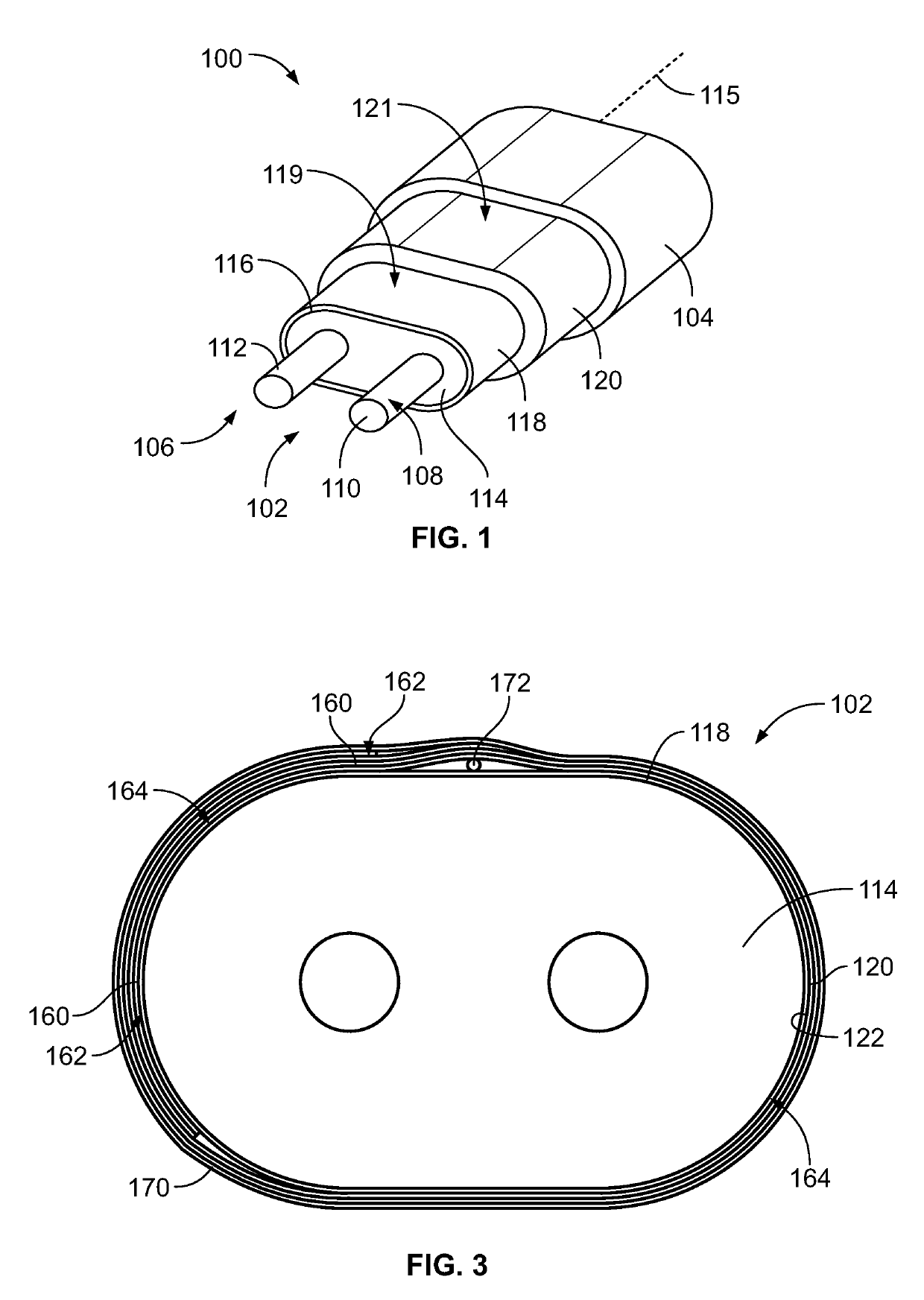
[0016]FIG. 1 is a perspective view of a portion of an electrical cable 100 formed in accordance with an embodiment. The electrical cable 100 may be used for high speed data transmission between two electrical devices, such as electrical switches, routers, and / or host bus adapters. The electrical cable 100 has a shielding structure configured to control capacitance and inductance relative to the signal conductors to control signal skew in the electrical cable 100 for high speed applications.

[0017]The electrical cable 100 includes a conductor assembly 102. The conductor assembly 102 is held within an outer jacket 104 of the electrical cable 100. The outer jacket 104 surrounds the conductor assembly 102 along a length of the conductor assembly 102. In FIG. 1, the conductor assembly 102 is shown protruding from the outer jacket 104 for clarity in order to illustrate the various components of the conductor assembly 102 that would otherwise be obstructed by the outer jacket 104. It is rec...


PUM

PropertyMeasurementUnit
dielectric constantaaaaaaaaaa
lengthaaaaaaaaaa
electricalaaaaaaaaaa

Abstract

An electrical cable includes a conductor assembly having a first conductor, a second conductor and an insulator surrounding the first conductor and the second conductor. The insulator has an outer surface and extends along a longitudinal axis for a length of the electrical cable. The conductor assembly has a coating layer on the outer surface of the insulator being conductive defining an inner electrical shield of the electrical cable. A cable shield is wrapped around the conductor assembly and has an inner edge and an outer edge. The outer edge is wrapped over the inner edge to form a flap covering the inner edge and extending along the longitudinal axis. The cable shield engages the inner electrical shield and forms an outer electrical shield exterior of the inner electrical shield.

Description

BACKGROUND OF THE INVENTION[0001]The subject matter herein relates generally to signal transmission electrical cables and shielding efficiency for signal conductors.[0002]Shielded electrical cables are used in high-speed data transmission applications in which electromagnetic interference (EMI) and / or radio frequency interference (RFI) are concerns. Electrical signals routed through shielded cables radiate less EMI / RFI emissions to the external environment than electrical signals routed through non-shielded cables. In addition, the electrical signals being transmitted through the shielded cables are better protected against interference from environmental sources of EMI / RFI than signals through non-shielded cables.[0003]Shielded electrical cables are typically provided with a cable shield formed by a tape wrapped around the conductor assembly. Signal conductors are typically arranged in pairs conveying differential signals. The signal conductors are surrounded by an insulator and th...

Claims


Application Information

Patent Timeline
Patent Type & Authority Applications(United States)
IPC IPC(8): H01B7/02H01B11/00H01B7/26H01B7/18H05K9/00H01B13/00H01B13/06
CPCH01B7/0275H01B13/0036H01B7/292H01B13/0016H01B7/2806H01B7/282H05K9/0098H01B7/1875H01B13/06H01B11/002H01B7/26H01B7/0216H01B11/06H01B7/17H01B7/0861H01B7/0208H01B11/1066H01B11/1016H01B11/1091
Inventor HORNUNG, CRAIG WARRENMORGAN, CHAD WILLIAM
Owner TYCO ELECTRONICS LOGISTICS AG (CH)
Why Eureka
Try Eureka