System And Method For Calibration Of An X-Ray Tube

a technology for x-ray tubes and calibration methods, applied in the field of diagnostic imaging systems and methods, can solve the problems of requiring significant time, x-ray tube to exceed focal spot tolerances, and high time and effort requirements for the calibration process of x-ray tubes, so as to reduce the time required for calibration, minimize damage, and minimize heat generation

Active Publication Date: 2019-10-24
GE PRECISION HEALTHCARE LLC
View PDF0 Cites 6 Cited by
  • Summary
  • Abstract
  • Description
  • Claims
  • Application Information

AI Technical Summary

Benefits of technology

[0012]In one exemplary embodiment of the present disclosure, a system and method for calibrating an X-ray tube is provided in which the X-ray tube includes an electronic storage medium associated with the X-ray tube on which calibration information for the X-ray tube is stored. The calibration information includes values representing the operating parameters for the focusing elements of the X-ray tube for desired focal spots that are determined during the initial testing of the X-ray tube after manufacture of the X-ray tube, as well as tolerance limits for variations in the focal spots. The stored calibration information also includes a number of gradient or sensitivity coefficient values corresponding to certain focal spot size functions, such as modulation transfer functions (MTF), for the X-ray tube that are employed to correct the operating parameters to achieve the desired focal spot size. This data is stored in a computer-readable format in the electronic storage medium and is accessed by the imaging system during a calibration procedure performed for the X-ray tube. In the procedure, the imaging system can operate the X-ray tube and focusing elements at the operating parameters specifie...

Problems solved by technology

The values determined for a particular X-ray tube within one imaging system, however, may cause the X-ray tube to exceed focal spot tolerances when the particular X-ray tube is coupled to another generator.
However, the process for the calibration of the X-ray tube is highly time and effort intensive.
In particular, in each of these situations where calibration is necessary, the number of calibration points that need to b...

Method used


Image

  • System And Method For Calibration Of An X-Ray Tube
  • System And Method For Calibration Of An X-Ray Tube
  • System And Method For Calibration Of An X-Ray Tube

Examples


Embodiment Construction

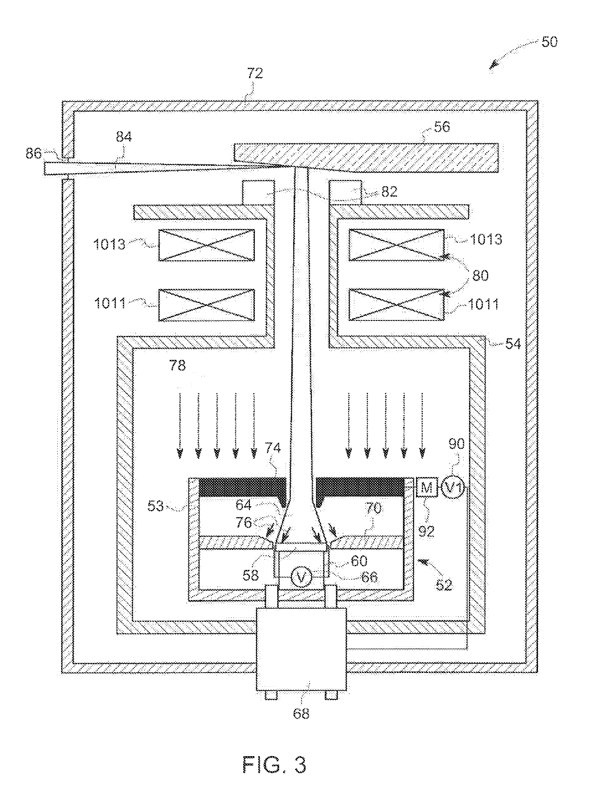
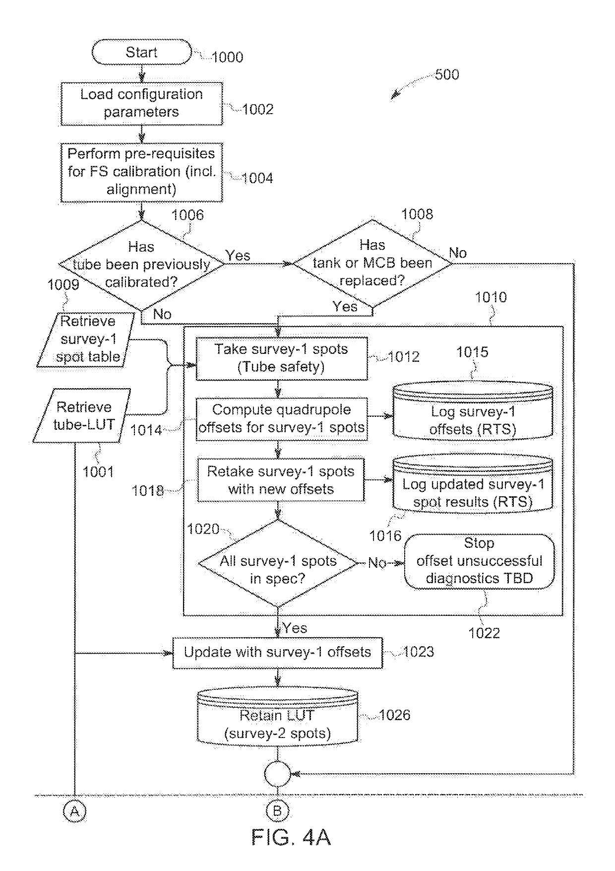
[0024]Embodiments of the present disclosure relate to calibration systems and processes for an X-ray tube operated with microsecond X-ray intensity switching. An exemplary X-ray tube and a computed tomography system employing the exemplary calibration system and method are presented.

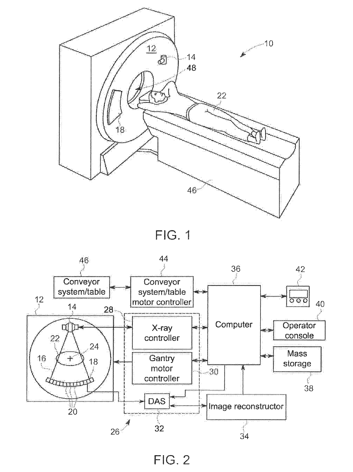
[0025]Referring now to FIGS. 1 and 2, as disclosed in U.S. Pat. No. 8,401,151 entitled X-ray Tube for Microsecond X-ray Intensity Switching, the entirety of which is expressly incorporated herein by reference, a computed tomography (CT) imaging system 10 is illustrated. The CT imaging system 10 includes a gantry 12. The gantry 12 has an X-ray source 14, which typically is an X-ray tube that projects a beam of X-rays 16 towards a detector array 18 positioned opposite the X-ray tube on the gantry 12. In one embodiment, the gantry 12 may have multiple X-ray sources (along the patient theta or patient Z axis) that project beams of X-rays. The detector array 18 is formed by a plurality of detectors 20 which t...


PUM


Abstract

A system and method for calibrating an X-ray tube is provided in which the X-ray tube includes an electronic storage medium associated with the X-ray tube on which calibration information for the X-ray tube is stored. The calibration information includes operating parameters for the focusing elements of the X-ray tube for desired focal spots, tolerance limits for variations in the focal spots and a number of gradient coefficient values corresponding to certain modulation transfer functions (MTF) for the X-ray tube that the imaging system can employ in an iterative manner to correct the operating parameters of the focusing elements to achieve the desired focal spot. This automatic iterative process significantly reduces the time required for the calibration of the X-ray tube. The system and method also employs scan sequencing to minimize the heat generated enabling the scans to be completed in a shorter amount of time than prior calibration processes.

Description

CROSS-REFERENCE TO RELATED APPLICATIONS[0001]This application claims priority from U.S. Provisional Patent Application Ser. No. 62 / 660,349, filed on Apr. 20, 2018, the entirety of which is expressly incorporated herein by reference for all purposes.BACKGROUND OF THE DISCLOSURE[0002]The disclosure relates generally to diagnostic imaging systems and methods, and more particularly, to a system and method for calibrating an X-ray tube.[0003]X-ray systems typically include an X-ray tube, a detector, and a support structure for the X-ray tube and the detector. In operation, an imaging support, on which an object is positioned, is located between the X-ray tube and the detector. The X-ray tube typically emits radiation, such as X-rays, toward the object. The radiation typically passes through the object on the support and impinges on the detector. As radiation passes through the object, internal structures of the object cause spatial variances in the radiation received at the detector. The...

Claims


Application Information

Patent Timeline
IPC IPC(8): A61B6/00G01T7/00H01J35/14H05G1/52H05G1/32
CPCG01T7/005H01J35/153H05G1/52H05G1/32A61B6/582H01J35/147A61B6/032A61B6/40
Inventor LEMAITRE, SERGIOBOUDRY, JOHNGABRIELSE, BRADLEYLEMMINGER, RYANCUTLER, SPENCER
Owner GE PRECISION HEALTHCARE LLC
Why Eureka
Try Eureka