Stackable hinge connection

a hinge connection and fixing technology, applied in the field of hinge connection, can solve the problems of inability to stabilize the hinge connection, disadvantage, and backlash, and achieve the effect of increasing the ease of use without losing the stability of the hinge connection

Inactive Publication Date: 2019-10-24
CLICFORMERS NV
View PDF5 Cites 7 Cited by
  • Summary
  • Abstract
  • Description
  • Claims
  • Application Information

AI Technical Summary

Benefits of technology

[0006]It is accordingly an object of the present invention to provide a hinge connection (1) comprising a male member (2) applied on a base plate (4) and a pair of female members (5) applied on a further base plate (7) wherein said male member has protrusions (8) provided to be hinged and resiliently fitted between a pair of female members (5) applied on said further base plate (7). The male member (2) is formed by two parallel male legs (3), wherein each leg comprises one of said protrusions, wherein said female member (5) is formed by two parallel female legs (6) and wherein each of said female members comprises a through hole (10) for engaging one of said protrusions, wherein the two parallel female legs (6) are connected by an intermediary piece (9) and wherein said through hole (10) extends through said female legs (6) and said intermediary piece (9). Typical for the present invention is that the protrusions (8) on each leg of the male member comprise cogs or cut teeth and that the through hole (10) of the female member (5) comprises cogs or cut teeth to accommodate the cogs or cut teeth of said male protrusions. Further, and also typical for the present invention is that the intermediary piece (9) and / or the female legs (6) of the female members (5) are interrupted, resulting in an increased ease of use without loss of stability of the hinge connection.

Problems solved by technology

A disadvantage of these smooth surfaces of both the protrusions and the through hole is that the hinge connection is not stable and quite some backlash is present.
In particular, the hinge connection allows the construction elements to rotate 180°, but because of the smooth surfaces it does not allow the construction elements to stay in certain fixed positions between 0° and 180°.
This is particularly disadvantageous when creating complex structures.
Another disadvantage of the hinge connection as disclosed in WO9830808 is that after fitting of the male member between a pair of female members, the hinge connection is firmly established and can only be disconnected by exerting a considerable amount of power.

Method used


Image

  • Stackable hinge connection
  • Stackable hinge connection
  • Stackable hinge connection

Examples


embodiment 1

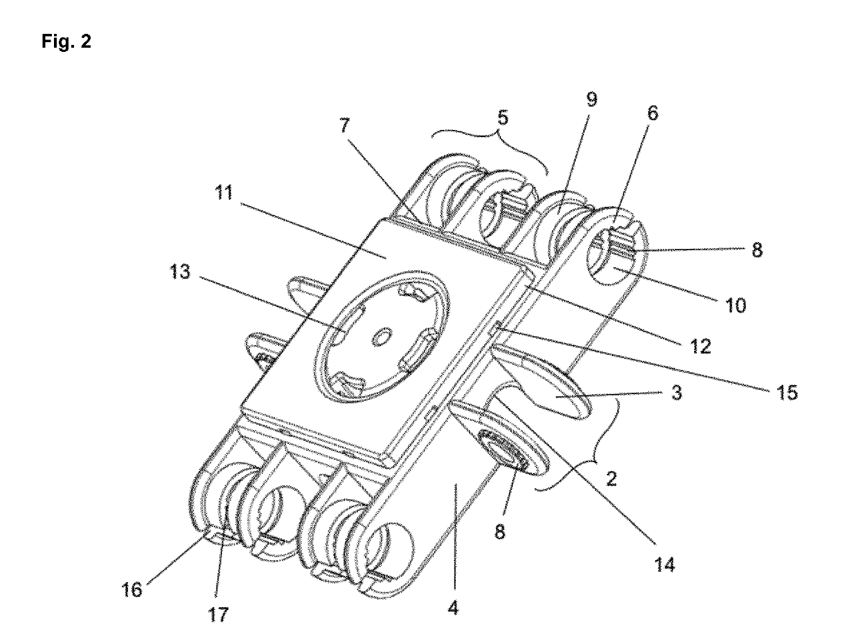
[0026]2. The hinge connection (1) , wherein the intermediary piece (9) of the female member (5) is mounted offset from the further base plate (7).

[0027]3. The hinge connection (1) according to embodiment 1 or 2, wherein the intermediary piece and the female legs (6) of the female member (5) are interrupted in the longitudinal direction (16).

[0028]4. The hinge connection (1) according to any one of the preceding embodiments, wherein the intermediary piece (9) of the female member (5) is interrupted in the transverse direction (17).

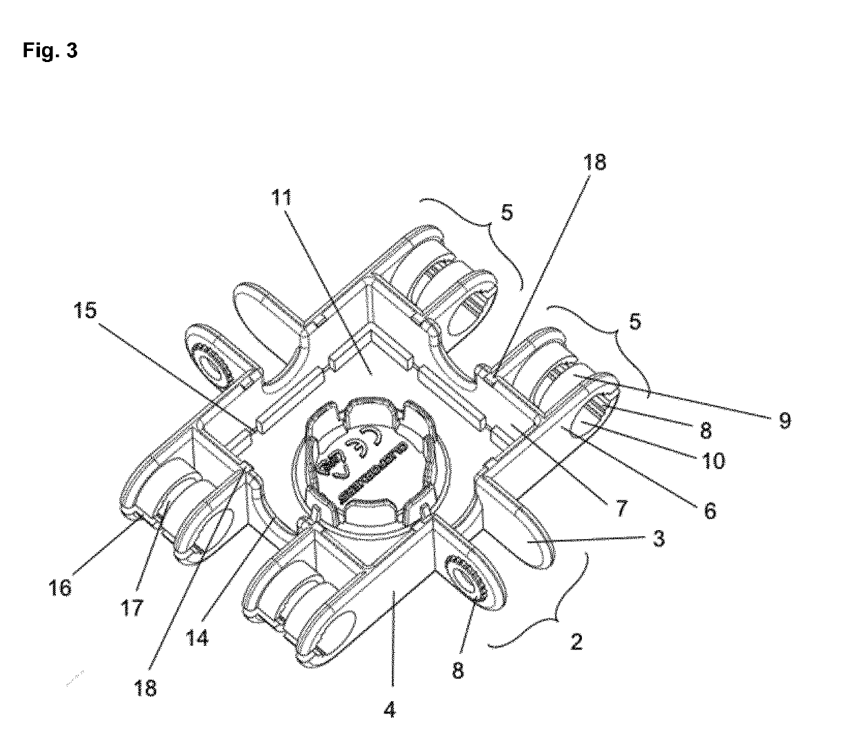
[0029]5. The hinge connection (1) according to any one of the preceding embodiments, wherein the intermediary piece (9) is cylindrical.

[0030]6. The hinge connection (1) according to any one of the preceding embodiments, wherein the male (2) and female (5) members are provided with rounded free ends.

[0031]7. The hinge connection (1) according to any one of the preceding embodiments, wherein the male (3) and female (6) legs comprise rounded borders.

[0032]8. A...

embodiment 9

[0036]12. A construction element (20) further comprising two linking members (21) applied on a base plate provided to be resiliently fitted on two female members, said female members formed by two parallel female legs and comprising a through hole and wherein the two parallel female legs are connected by an intermediary piece and wherein said through hole extends through said female legs and said intermediary piece, characterized in that the linking member (21) comprises a C-shaped curved leg (22).

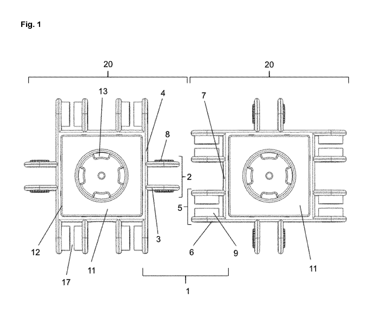
[0037]13. A construction element (20) according to anyone of embodiments 8 to 12, comprising a connection plate (11) that connects the base plates (4) and / or the further base plates (7) and extends in a plane perpendicular to said base plates.

embodiment 13

[0038]14. A construction element (20) further comprising a connection plate (11) that connects the two base plates (4) and the two further base plates (7) and extends in a plane perpendicular to said base plates.

[0039]15. The construction element (20) according to embodiment 13 or 14, wherein the connection plate (11) comprises a ridge (12) at the connections between the connection plate (11) and the base plates (4) and further base plates (7).


PUM


Abstract

The present invention relates to a hinge connection comprising a male member applied on a base plate, and having protrusions provided to be hinged and resiliently fitted between a pair of female members applied on a further base plate. The male member of the hinge connection is being formed by two parallel male legs, wherein each leg comprises protrusions comprising cogs or cut teeth. The female member is formed by two parallel female legs and each of the female members comprises a through hole for engaging said protrusions of the male legs. The present invention further provides construction elements comprising the hinge connection members of the instant application. In a particular embodiment such construction elements are stackable, and allow the construction of complex three-dimensional structures without loss of flexibility.

Description

FIELD OF THE INVENTION[0001]The present invention relates to a hinge connection comprising a male member applied on a base plate and a pair of female members applied on a further base plate, said male member having protrusions provided to be hinged and resiliently fitted between the pair of female members applied on a further base plate. The male member of the hinge connection is being formed by two parallel male legs, wherein each leg comprises protrusions comprising cogs or cut teeth. The female member is formed by two parallel female legs and each of the female members comprises a through hole for engaging said protrusions of the male legs. The present invention further provides construction elements comprising the hinge connection members of the instant application. In a particular embodiment such construction elements are stackable, and allow the construction of complex three-dimensional structures without loss of flexibility.BACKGROUND TO THE INVENTION[0002]Hinge connections a...

Claims


Application Information

Patent Timeline
Patent Type & Authority Applications(United States)
IPC IPC(8): A63H33/08A63H33/06
CPCA63H33/067A63H33/065A63H33/08A63H33/062A61H1/0292
Inventor PARK, KEE YOUNGVAN ROY, HEDWIG
Owner CLICFORMERS NV
Why Eureka
Try Eureka