Method for producing a composite material, and composite material

a composite material and method technology, applied in the field of producing composite materials, can solve the problems of not being able to produce, or only at enormous cost, according to traditional methods, and achieve the effect of reducing the cost of production

Active Publication Date: 2019-10-24
WICKEDER WESTFALENSTAHL
View PDF0 Cites 1 Cited by
  • Summary
  • Abstract
  • Description
  • Claims
  • Application Information

AI Technical Summary

Benefits of technology

[0029]In a further advantageous embodiment of the invention, it can be provided that the filling channel or filling channels a

Problems solved by technology

That part of the filler strip which is extruded into the filling channel accordingly forms to some extent a narr

Method used


Image

  • Method for producing a composite material, and composite material
  • Method for producing a composite material, and composite material
  • Method for producing a composite material, and composite material

Examples


Embodiment Construction

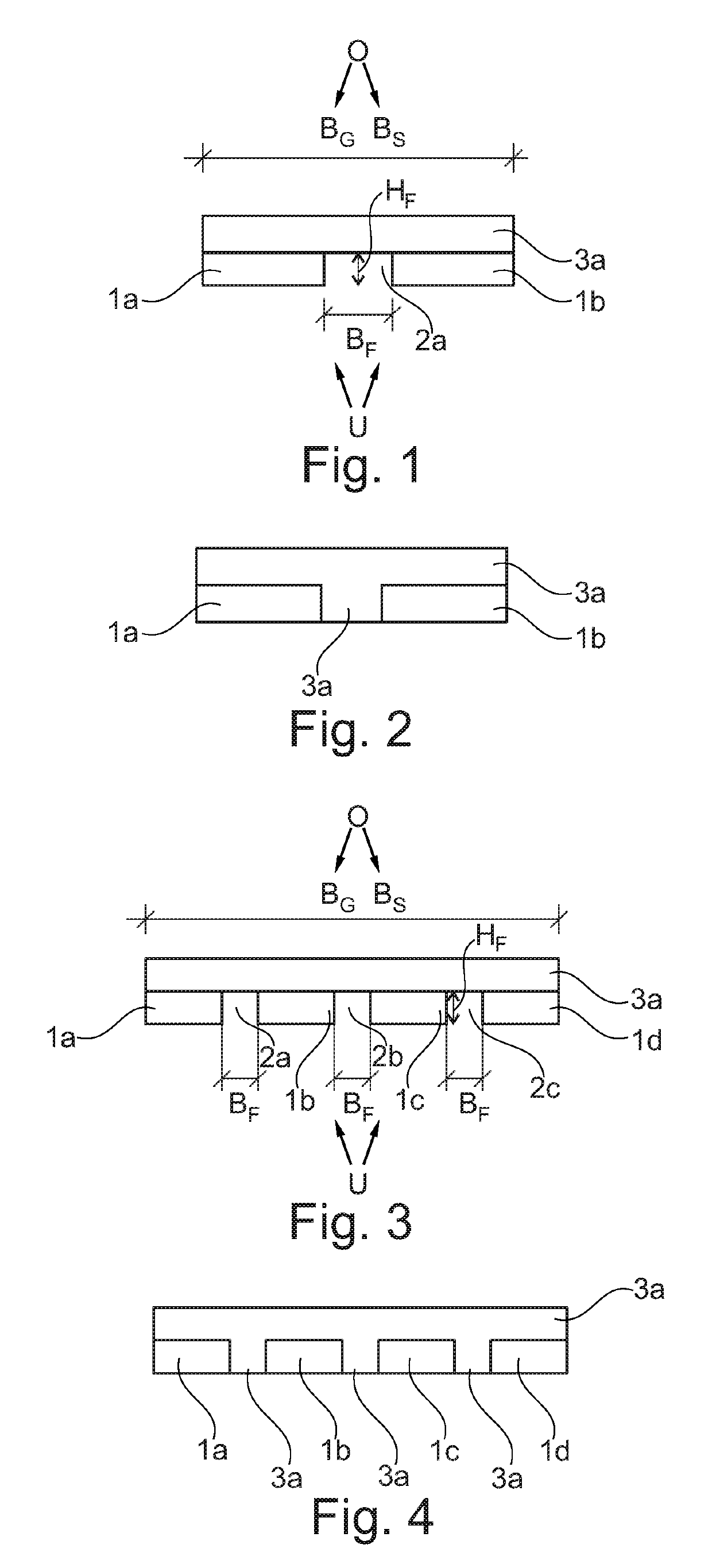
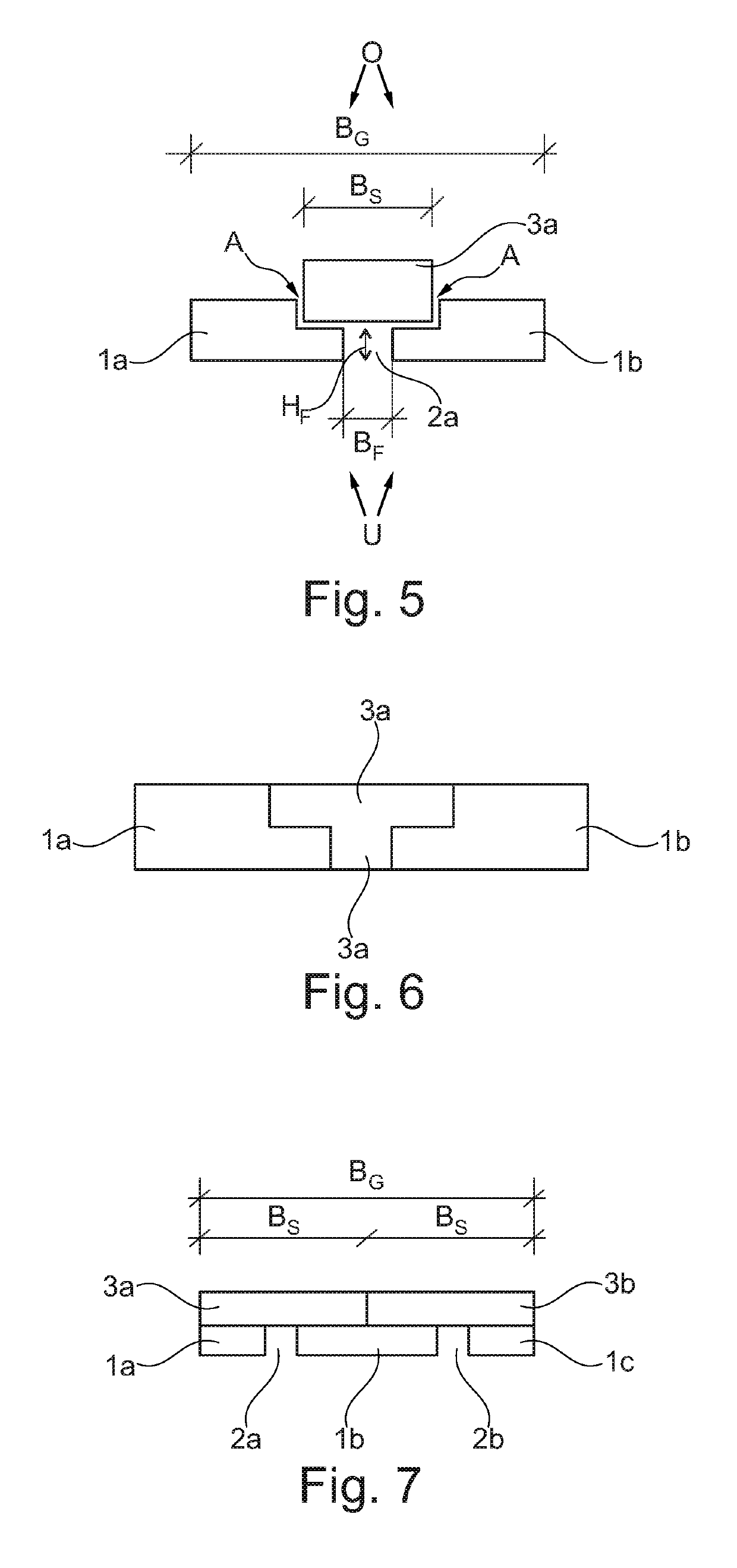
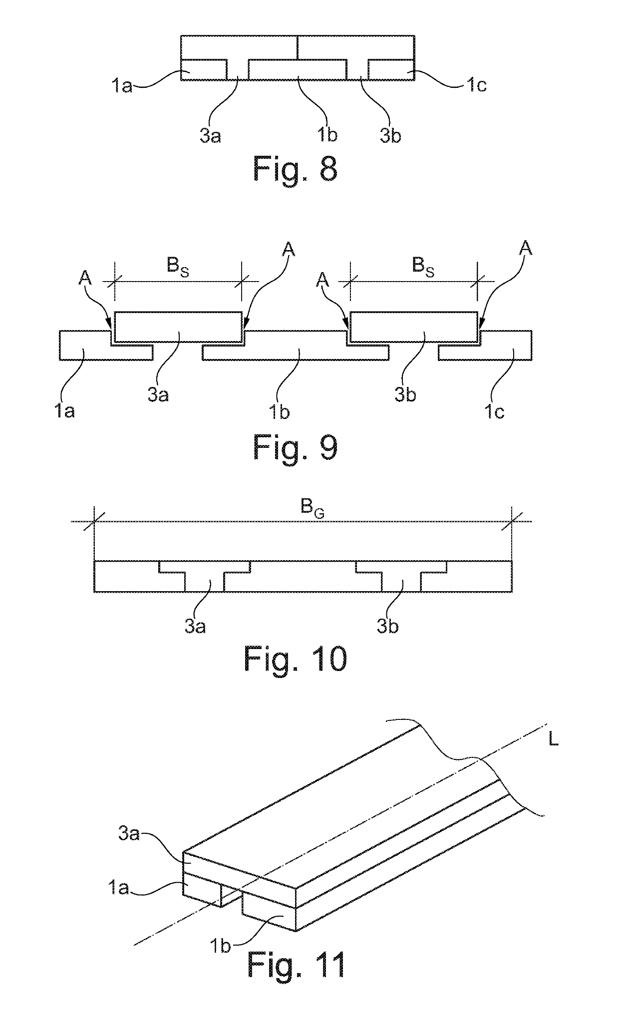
[0045]The proportions in the figures do not necessarily correspond to the real proportions, but serve substantially for illustrative purposes.

[0046]The following reference symbols are used in the figures:[0047]L longitudinal axis[0048]BG total width[0049]BF width of the filling channel[0050]HF height of the filling channel[0051]BS width of the filler strip[0052]A recess[0053]top side[0054]U bottom side[0055]1a (first) strip[0056]1b (second) strip[0057]1c (third) strip[0058]1d (fourth) strip[0059]2a filling channel[0060]2b (second) filling channel[0061]2c (third) filling channel[0062]3a filler strip[0063]3b (second) filler strip

[0064]In the method proposed according to the invention, a band arrangement is fed to a roll plating device (not represented) or to the inlet of a roll plating device and leaves the roll plating device or the outlet as a plated composite material. A preferred plating method for the present invention is constituted by the roll plating. In principle, other plati...


PUM

PropertyMeasurementUnit
Pressureaaaaaaaaaa
Tensile strengthaaaaaaaaaa

Abstract

A method for producing a composite material by plating a band arrangement with a top side (O) and a bottom side (U), wherein the band arrangement comprises at least a first strip and a second strip, which form between them a filling channel, wherein the band arrangement comprises at least one filler strip, wherein the abovementioned band arrangement is plated, wherein a part of the filler strip, during the plating, is extruded into the filling channel; and a composite material, characterized in that it has been produced according to the method as disclosed.

Description

FIELD OF THE INVENTION[0001]The present invention relates to a method for producing a composite material as disclosed herein, and to a composite material as disclosed herein.BACKGROUND[0002]A method for producing a composite material by plating has become known, for instance, from PCT / US15 / 41857. Here, a method for producing a composite material by means of cold rolling, in which different metal strips are joined side by side, is described. A plurality of metal strips are herein brought together on the inlet side, both side by side and one above another, such that the material fed to the roll gap of the roll stand has a continuous rectangular cross section. In addition, the strip widths on the inlet side are chosen such that overlaps are obtained between the strips guided one above another (comparable to the type of bond / offset used in bricklaying). By the subsequent cold roll plating process, adhesion between the overlapping material surfaces is established, and in this way a compo...

Claims


Application Information

Patent Timeline
IPC IPC(8): B21B1/38B32B15/01B23K20/04
CPCB32B15/013B21B2001/383B21B1/38B32B15/012B23K20/04B32B15/01B21K23/00B21K25/00B23K2101/16B23K2101/18B21C23/00
Inventor BALKENHOL, MICHAELERLEMEYER, JENS
Owner WICKEDER WESTFALENSTAHL
Why Eureka
Try Eureka