Swivel snaphook

a snaphook and swivel technology, applied in the field of snaphooks, can solve the problems of easy rocking and swinging mechanical wear to the connecting shaft or through hole, and achieve the effect of avoiding the noise generated by the friction and collision between the connecting shaft and the through hole during use, stable mechanical properties of the connecting shaft, and prolonging the service life of the swivel snaphook

Active Publication Date: 2019-10-24
DURAFLEX HONG KONG
View PDF12 Cites 2 Cited by
  • Summary
  • Abstract
  • Description
  • Claims
  • Application Information

AI Technical Summary

Benefits of technology

[0024]The implementation of the swivel snaphook provided in the present invention can achieve the following beneficial effects: in the swivel snaphook provided in the present invention, the retainer comprises a support portion and a strap mounting portion, and the support portion comprises a base body connected to the strap mounting portion, a through hole passing through the base body, and a snap-in portion protruding from the surface of the base body and surrounding the through hole; and the hook comprises a hook and connector portion and an engaging portion, and the engaging portion comprises a connecting shaft connected to the hook and connector portion, and a snap-on portion. When the hook and the retainer are snap-fitted together, the snap-on portion surrounds the snap-in po

Problems solved by technology

Apparently, such a simple engaging method has the following disadvantages: in order to ensure that the connecting shaft can swivel freely relative to the through hole, a gap space is definitely provided between the connecting shaft and the through hole.
As a result, the

Method used


Image

  • Swivel snaphook
  • Swivel snaphook
  • Swivel snaphook

Examples


first embodiment

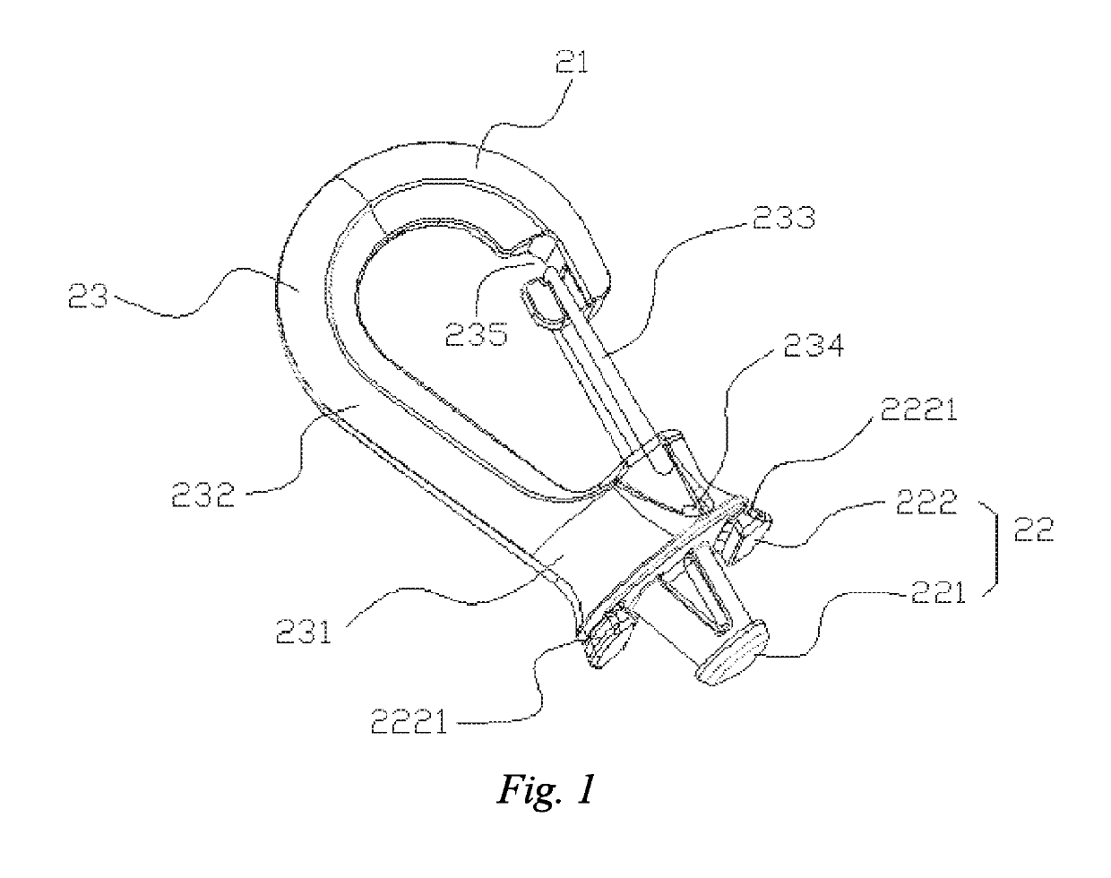
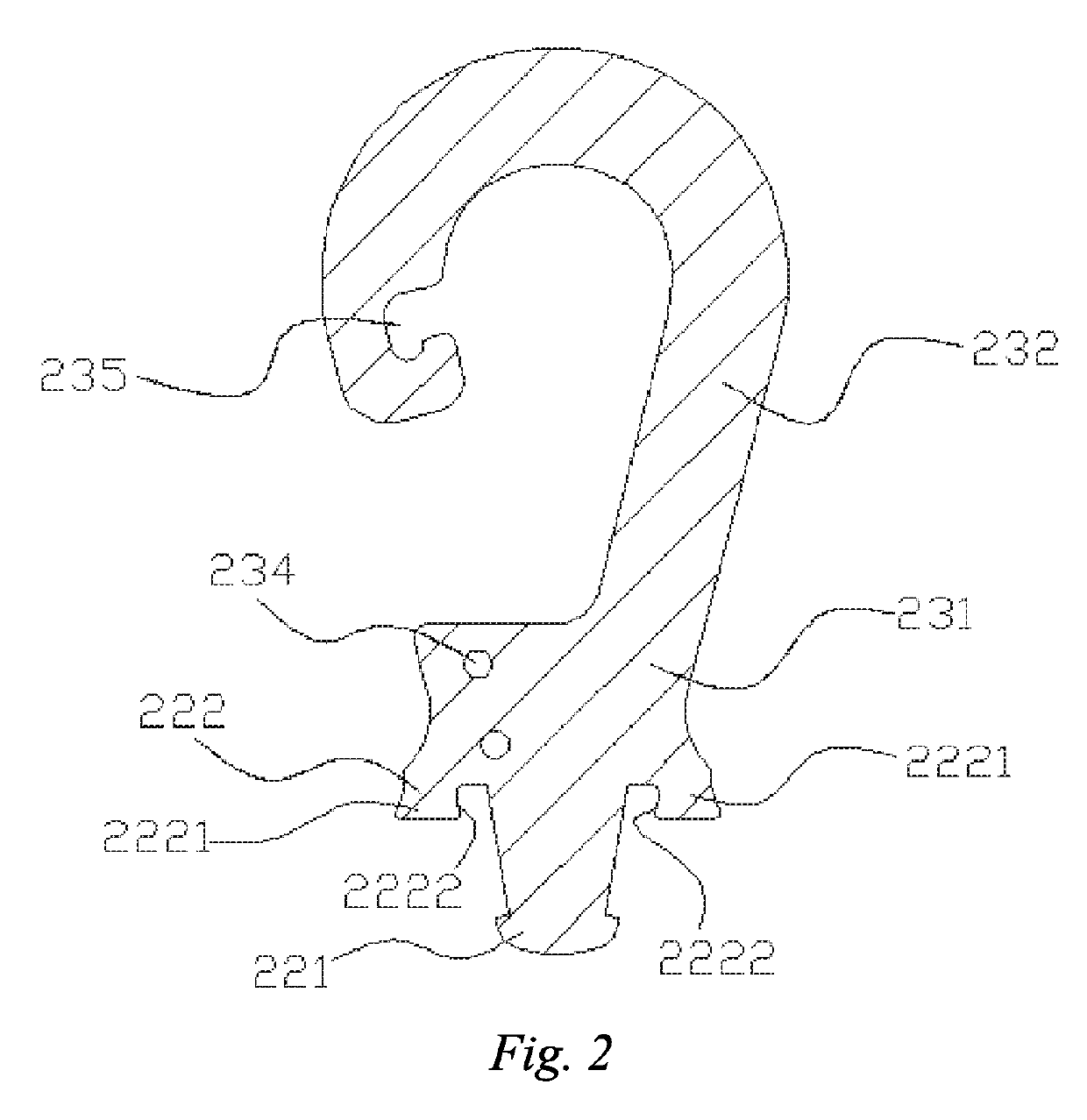
[0036]As shown in FIG. 7, this embodiment provides a swivel snaphook, which comprises a hook 200 and a retainer 100. The retainer 100 and the hook 200 are snap-fitted together, and the retainer 100 and the hook 200 can swivel relative to each other after being snap-fitted, so that the swivel snaphook is more flexible during use. Furthermore, the retainer 100 and the hook 200 have an integral structure made of a plastic material. It may be understood that the material of the retainer 100 and the hook 200 is not merely limited to a plastic or resin material, and may be a metal material, a composite material of resin and metal or, in addition to these, another common material.

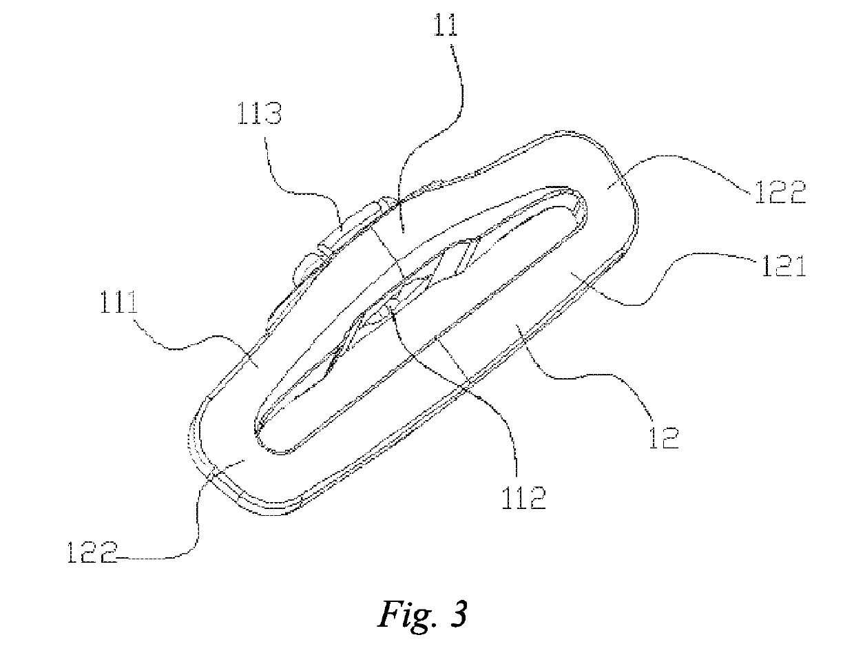
[0037]As shown in FIG. 3 to FIG. 5, the retainer 100 comprises a support portion 11 used to connect the hook 200 and a strap mounting portion 12 used to connect a fabric strap. Specifically, the strap mounting portion 12 comprises a cross bar 121, and two lateral bars 122 respectively bending and extending from tw...

second embodiment

[0050]This embodiment provides a swivel snaphook which is different from that in the first embodiment in that:

[0051]the boss 2221 has a protrusion protruding from the surface of the boss 2221 that faces the connecting shaft 221. When the hook 200 and the retainer 100 are snap-fitted, the protrusion is located between the snapping boss 1132 and the surface of the base body 111, so that the protrusion and the snapping boss 1132 abut against each other to form a snap fit in an inverted manner.

[0052]Compared with the first embodiment, the fit between the boss 2221 and the snapping boss 1132 is more stable and reliable, so that not only the relative collision between the connecting shaft 221 and the through hole 112 can be avoided, and to a certain extent the hook 200 is also prevented from being detached from the retainer 100.

third embodiment

[0053]This embodiment provides a swivel snaphook which is different from that in the first embodiment in that: the plurality of bosses 2221 are joined to each other to form an annular boss.

[0054]Compared with the first embodiment, when the hook 200 and the retainer 100 are snap-fitted, the annular boss formed by the plurality of bosses 2221 may completely cover the snapping boss 1132 to increase the abutting area between the boss 2221 and the snapping boss 1132 to the greatest extent, so that the fit between the snap-on portion 222 and the snap-in portion 113 is more stable, and the relative collision between the connecting shaft 221 and the through hole 112 is better prevented.


PUM


Abstract

A swivel snaphook has a hook and a retainer. The retainer comprises a support portion and a strap mounting portion. The support portion has a base body connected to the strap mounting portion, a through hole passing through the base body, and a snap-in portion protruding from the surface of the base body and surrounding the through hole. The hook has a hook and connector portion and an engaging portion. The engaging portion has a connecting shaft connected to the hook and connector portion, and a snap-on portion. When the hook and the retainer are snap-fitted together, the snap-on portion surrounds the snap-in portion and fits with the snap-in portion in an inverted manner.

Description

TECHNICAL FIELD[0001]The present invention relates to the technical field of human daily necessities, and specifically relates to a snaphook.BACKGROUND ART[0002]Nowadays, swivel snaphooks become increasingly popular in people's daily life. At present, a common commercially available swivel snaphook typically comprises a hook and a retainer that are snap-fitted together and can swivel relative to each other. The retainer comprises a support portion and a strap mounting portion used to connect a fabric strap. The hook comprises a hook and connector portion used to hook an object and a connecting shaft mounted on the support portion. The support portion typically comprises a base body connected to the strap mounting portion and a through hole passing through the base body. The connecting shaft is inserted in the through hole, so that the hook and the retainer are engaged.[0003]Apparently, such a simple engaging method has the following disadvantages: in order to ensure that the connect...

Claims


Application Information

Patent Timeline
IPC IPC(8): F16B45/02F16G15/08
CPCF16B45/02F16G15/08A44B13/00F16B45/00F16B21/07F16B45/036F16B45/008
Inventor CHAN, YICK FAI
Owner DURAFLEX HONG KONG
Why Eureka
Try Eureka