Check patentability & draft patents in minutes with Patsnap Eureka AI!

Data processing system

Inactive Publication Date: 2019-10-24
ROLLS ROYCE POWER ENG PLC
View PDF0 Cites 1 Cited by
  • Summary
  • Abstract
  • Description
  • Claims
  • Application Information

AI Technical Summary

Benefits of technology

This technology provides a better way to monitor and control the operation of instruments in a monitoring system. It uses pre-generated images and other graphics to represent the current status of the instrument in a more intuitive and user-friendly way than traditional control systems. This helps users to easily identify and analyze the available options and parameters. The technology also reduces the need for individual meters and mechanical indications, saving space and money. The overall system is controlled by logical circuits implemented in an FPGA-based system, which provides more reliable and deterministic performance.

Problems solved by technology

Consequently, conventional control and monitoring system designs are very conservative, using only simple components with well-defined behaviour.
However, presenting the current condition of the operation parameters of all plant instrumentation on simple meters and indicators can be non-intuitive and requires highly skilled operators to analyse and act on the information presented in a safe and efficient manner.

Method used


Image

  • Data processing system
  • Data processing system
  • Data processing system

Examples


Embodiment Construction

[0076]Like reference numerals will be used, where appropriate, for like features shown in the Figures.

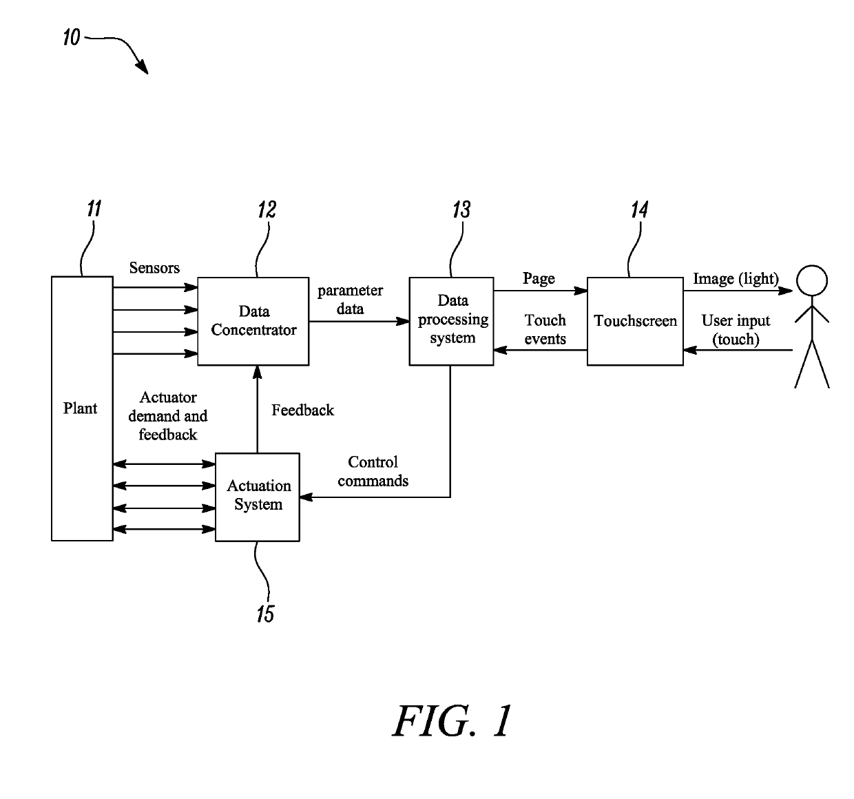
[0077]FIG. 1 is a schematic illustration of the overall system data flow in a plant control and monitoring system 10. As can be seen in FIG. 1, the system comprises a plant 11, a data concentrator 12, a data processing system 13, a touchscreen 14 and an actuation system 15.

[0078]The control and monitoring system 10 may monitor the (e.g. current) condition of multiple operation parameters of the plant 11 via sensors which provide signals representing the measured conditions to a data concentrator 12. The data concentrator 12 is a pre-processing module and operates to convert signals representing the measured conditions into appropriate parameter data of a type that is suitable for use by the data processing system 13. The data concentrator 12 may also be responsible for validating sensor inputs. The parameter data may be sent to the data processing system 13 at predefined time interv...


PUM


Abstract

There is disclosed a data processing system for generating pages of image data to be displayed in a monitoring system which monitors the condition of one or more instrument operation parameters. The data processing system comprising a display sub-system configured to receive parameter data representing the condition of one or more operation parameters being monitored and read a set of configuration data for a page to be displayed, wherein the set of configuration data indicates a configuration of a page for displaying a group of at least one operation parameter of the one or more operation parameters being monitored. The display sub-system is further configured to generate a page to be displayed based on the parameter data, the configuration data and pre-generated image data stored in memory.

Description

CROSS-REFERENCE TO RELATED APPLICATIONS[0001]This specification is based upon and claims the benefit of priority from UK Patent Application Number 1806292.7 filed on 18 Apr. 2018, the entire contents of which are incorporated herein by reference.TECHNICAL FIELD[0002]The present disclosure concerns a data processing system, in particular a data processing system for generating pages of image data for display in a (e.g. control and) monitoring system, e.g. of an instrumentation plant.BACKGROUND[0003]It is known in the art that nuclear steam raising plant instrumentation systems are required to be designed so that they behave in safe deterministic ways under normal and abnormal / fault conditions.[0004]Consequently, conventional control and monitoring system designs are very conservative, using only simple components with well-defined behaviour. For example, reactor control rooms traditionally present the current operation parameter conditions of all plant instrumentation on simple meter...

Claims


Application Information

Patent Timeline
IPC IPC(8): G06F3/0483G06F11/30G06F11/32G06F3/0482G06F3/0488
CPCG06F11/3058G06F3/0483G06F3/0482G06F3/04883G06F11/328G06F11/3089G01D13/00G06F3/0481G06F3/0488G05B19/418G05B2219/31469G05B2219/31472G21D3/001G21D3/008Y02E30/00
Inventor GRESHAM, ALAN T.REEVE, MARK D.BERESFORD, LEE R.FRANKLIN, MARK W.
Owner ROLLS ROYCE POWER ENG PLC
Features
  • R&D
  • Intellectual Property
  • Life Sciences
  • Materials
  • Tech Scout
  • Unparalleled Data Quality
  • Higher Quality Content
  • 60% Fewer Hallucinations
Learn More