Power-factor correcting converter

a converter and power factor technology, applied in the field of power factor correcting converters, can solve the problems of reducing increasing the conduction loss, and preventing the reduction in the size so as to improve the efficiency of the power factor correcting converter, reduce the effective value of the inductor current, and reduce the conduction loss

Active Publication Date: 2019-10-24
PANASONIC INTELLECTUAL PROPERTY MANAGEMENT CO LTD
View PDF0 Cites 5 Cited by
  • Summary
  • Abstract
  • Description
  • Claims
  • Application Information

AI Technical Summary

Benefits of technology

[0034]The power-factor correcting converters according to the aspects of the present disclosure, in which any of the switch circuits in the inductor current discharge path is turned off and operates as a diode in the vicinity of the zero cross point of the inp

Problems solved by technology

However, in a case where a large amount of electric power is handled, in particular, conduction loss in the bridge diode degrades the efficiency of the power-factor correcting converter and prevents reduction in size of the power-factor correcting converter.
Therefore, althoug

Method used


Image

  • Power-factor correcting converter
  • Power-factor correcting converter
  • Power-factor correcting converter

Examples


embodiment 1

[0062]The following describes the power-factor correcting converter according to Embodiment 1 of the present disclosure with reference to the drawings.

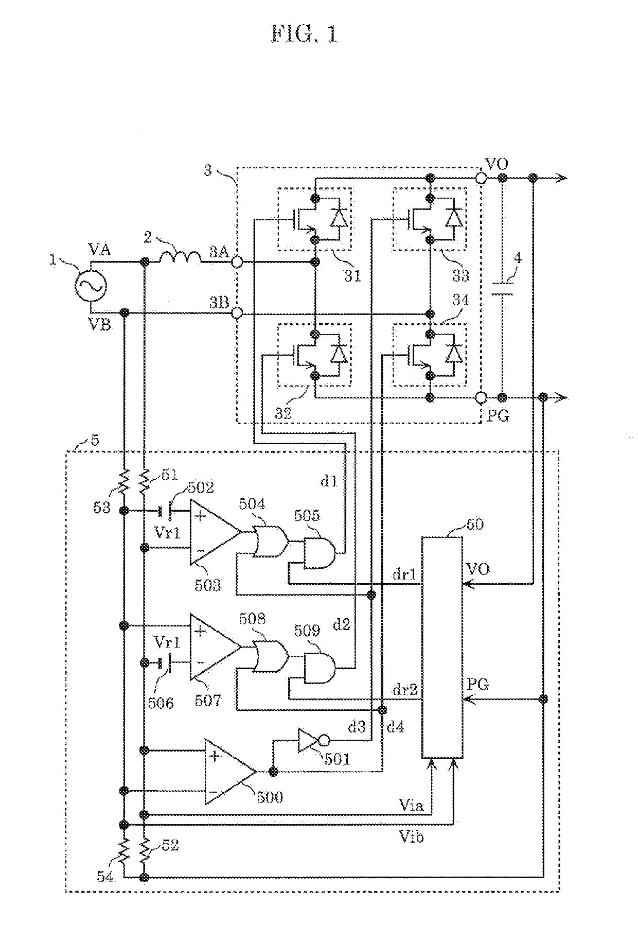
[0063]FIG. 1 is a circuit configuration diagram of a power-factor correcting converter according to Embodiment 1. The power-factor correcting converter according to the present embodiment includes inductor2, bridge circuit 3, output capacitor 4, and control circuit 5, as shown in FIG. 1.

[0064]Input AC power source 1 is connected to first power source terminal VA and second power source terminal VB and outputs input AC voltage Vi to first power source terminal VA and second power source terminal VB. Inductor 2 is connected in series to input AC power source 1. Bridge circuit 3 receives input AC voltage Vi at first input terminal 3A and second input terminal 3B via inductor 2. Output capacitor 4 is connected to output terminals VO and PG of bridge circuit 3 and outputs output DC voltage Vo. Bridge circuit 3 includes first higher-potenti...

embodiment 2

[0098]FIG. 9 is a circuit configuration diagram of a power-factor correcting converter according to Embodiment 2. FIG. 10 shows waveforms of the operating power-factor correcting converter according to Embodiment 2. FIG. 11A shows the current path of the power-factor correcting converter according to Embodiment 2 in the case of the positive phase, and FIG. 11B shows the current path of the power-factor correcting converter according to Embodiment 2 in the case of the negative phase. In FIG. 9, the same components as those of the power-factor correcting converter according to Embodiment 1 shown in FIG. 1 have the same reference numerals and will not be described. The power-factor correcting converter according to Embodiment 2 differs from the power-factor correcting converter according to Embodiment 1 in FIG. 1 in terms of the configuration of the control circuit, and the control circuit in the present embodiment is called control circuit 5A to be distinguished from control circuit 5...

embodiment 3

[0103]FIG. 12 is a circuit configuration diagram of a power-factor correcting converter according to Embodiment 3. In FIG. 12, the same components as those of the power-factor correcting converters according to Embodiment 1 shown in FIG. 1 and Embodiment 2 shown in FIG. 9 have the same reference numerals and will not be described. The power-factor correcting converter according to the present embodiment differs from the power-factor correcting converters according to Embodiments 1 and 2 in terms of the configuration of the control circuit, and the control circuit in the present embodiment is called control circuit 5B to be distinguished from control circuits in Embodiments 1 and 2. Control circuit 5B differs from control circuit 5A of the power-factor correcting converter according to Embodiment 2 in terms of the following points: That is, first reference voltage source 502, second reference voltage source 506, comparators 503 and 507, OR circuits 504 and 508, and AND circuits 505 a...


PUM


Abstract

A power-factor correcting converter includes: a series circuit including a first higher-potential switch and a first lower-potential switch connected in series to each other; and another series circuit including a second higher-potential switch and a second lower-potential switch connected in series to each other. In a positive phase period of the input AC voltage, a control circuit turns off the second higher-potential switch, turns on the second lower-potential switch, and alternately turns on and off the first lower-potential switch as a master switch and the first higher-potential switch as a slave switch. In a negative phase period of the input AC voltage, the control circuit reverses the on/off operation and the master/slave relationship, and turns on and off only the master switch and turns off the slave switch when the absolute value of the input AC voltage is smaller than or equal to a predetermined value.

Description

CROSS REFERENCE TO RELATED APPLICATIONS[0001]This application is a U.S. continuation application of PCT International Patent Application Number PCT / JP2017 / 046280 filed on Dec. 25, 2017, claiming the benefit of priority of Japanese Patent Application Number 2017-001342 filed on Jan. 6, 2017, the entire contents of which are hereby incorporated by reference.BACKGROUND1. Technical Field[0002]The present disclosure relates to a power-factor correcting converter having the function of converting AC input voltage into desired output DC voltage and shaping the input AC current waveform.2. Description of the Related Art[0003]In recent years, to suppress harmonic current, a power-factor correcting converter that corrects the power factor by shaping an input current waveform in such a way that the input current waveform follows an input AC voltage waveform is frequently used as an input section of a power source circuit connected to an AC input. In a typical power-factor correcting converter,...

Claims


Application Information

Patent Timeline
IPC IPC(8): H02M1/42H02M7/219H02J7/04
CPCH02J7/041H02M7/219H02M2001/0003H02M1/4225H02M1/4233Y02B70/10Y02P80/10H02M1/0085H02J7/0071H02M1/0003
Inventor HASHIMOTO, TAKAOISHII, TAKUYA
Owner PANASONIC INTELLECTUAL PROPERTY MANAGEMENT CO LTD
Why Eureka
Try Eureka