
Induction heating device having improved control algorithm and circuit structure

Active Publication Date: 2019-10-24
LG ELECTRONICS INC
View PDF0 Cites 0 Cited by
  • Summary
  • Abstract
  • Description
  • Claims
  • Application Information

AI Technical Summary

Benefits of technology

The present disclosure provides an induction heating device with improved object detection and heating-region control using a flexible mode. The device includes a control unit for detecting the presence or absence of an object based on individual coil-based object-detection and coil set-based object-detection results. The circuit configuration of the device allows for inversion or switching of the current direction to improve heating-region control and high-power performance. The device also reduces the object heating time and improves heating intensity adjustment accuracy, resulting in shorter cooking timing and improved user satisfaction.

Problems solved by technology

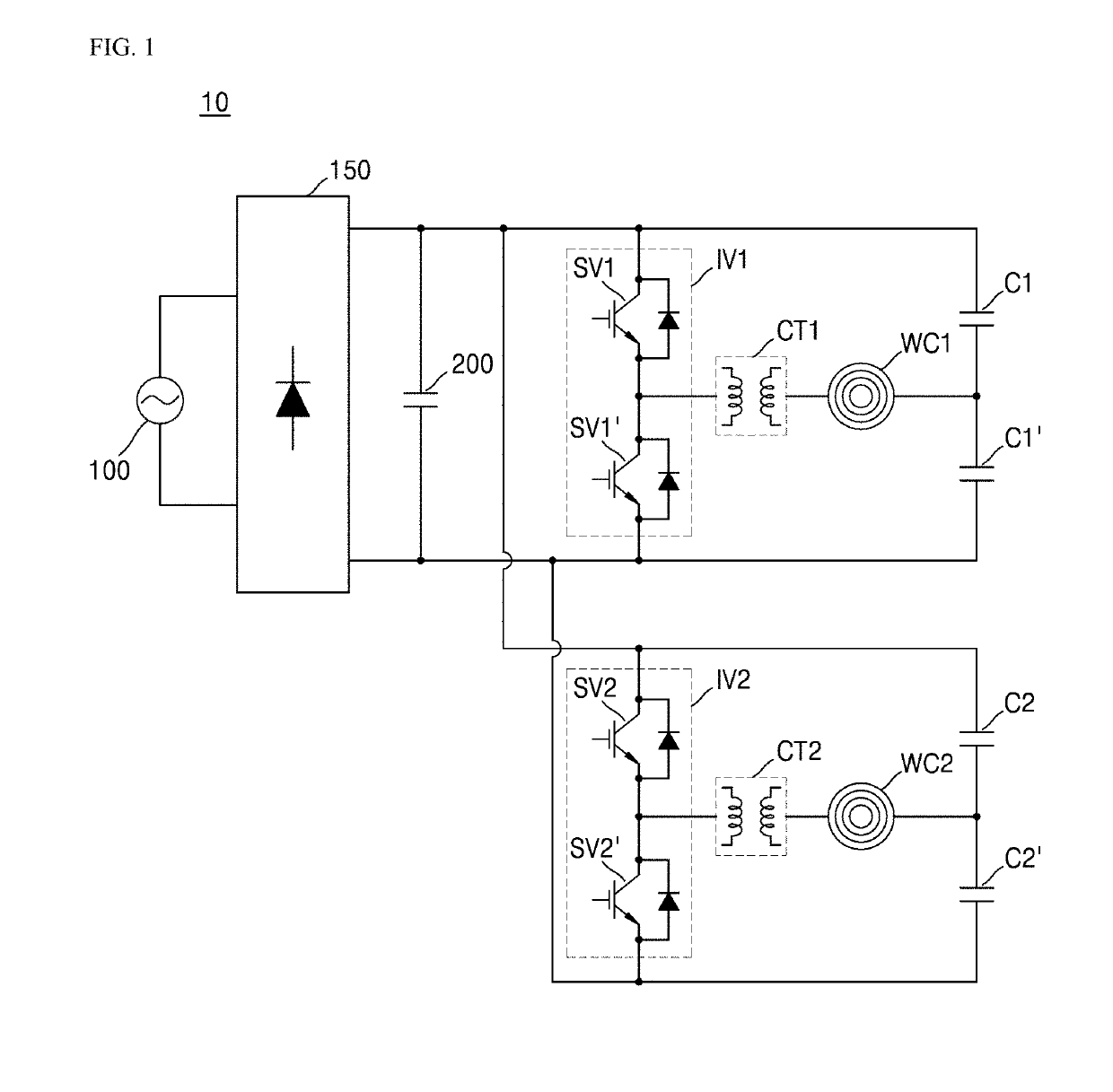
Further, there is no circuit configuration capable of reversing or switching the direction of the current input / output to / from the working coils.
This may lead to a problem that the heated region is concentrated on the edges of the working coils WC1 and WC2 and, hence, the heated region of the object is limited to the region corresponding to the edges of the working coils WC1 and WC2.
Thus, when the object is located on a region corresponding to an area between the first and second working coils WC1 and WC2, the device may not accurately detect whether the object is disposed on at least one of the first and second working coils WC1 and WC2.
In this case, even when the induction heating device 10 is set to the flex mode, the device cannot correctly execute the flex mode.
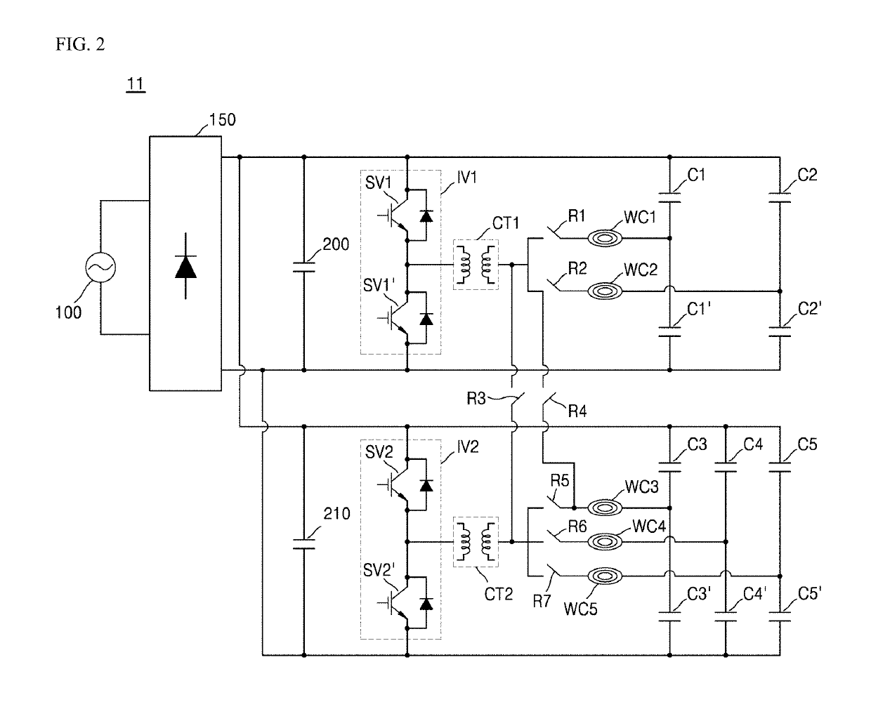
In this connection, there is no circuit configuration that allows inverting or switching the direction of the current input and output to and from the working coil.
Thus, for example, when an object is located in a region corresponding to a position between the first and second working coils WC1 and WC2, the device may not accurately detect whether the object is disposed on at least one of the first and second working coils WC1 and WC2.
In this case, even when the induction heating device 11 is set to the flex mode, the device 11 cannot correctly execute the flex mode.
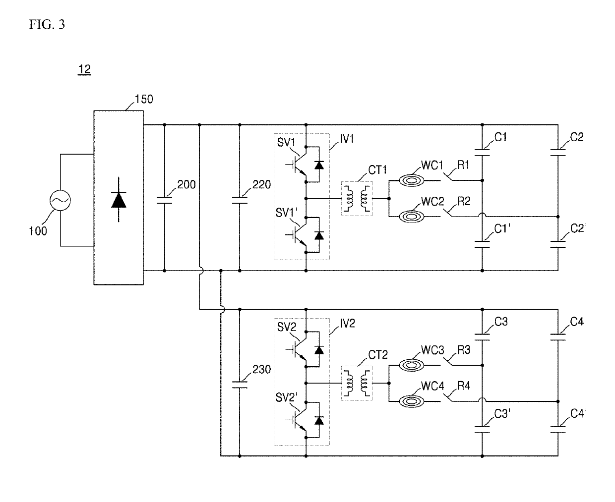
In this connection, there is no circuit configuration that allows inverting or switching the direction of the current input and output to and from the working coil.
The circuit structure and object-detection method as described above may lead to following defects: when the device operates in the flex mode, corresponding working coils may be controlled only at an in-phase and at the same frequency; further, when an object is located on a region corresponding to an area between the working coils, the flex mode is not implemented properly; further, realizing a high output performance requires a separate bridge diode or a separate synchronization scheme.

Method used


Image

  • Induction heating device having improved control algorithm and circuit structure
  • Induction heating device having improved control algorithm and circuit structure
  • Induction heating device having improved control algorithm and circuit structure

Examples


Embodiment Construction

[0041]The above objects, features and advantages will become apparent from the detailed description with reference to the accompanying drawings. Embodiments are described in sufficient detail to enable those skilled in the art in the art to easily practice the technical idea of the present disclosure. Detailed descriptions of well-known functions or configurations may be omitted in order not to unnecessarily obscure the gist of the present disclosure. Hereinafter, embodiments of the present disclosure will be described in detail with reference to the accompanying drawings. Throughout the drawings, like reference numerals refer to like elements.

[0042]FIG. 4 is a circuit diagram showing an induction heating device according to one embodiment of the present disclosure.

[0043]Referring to FIG. 4, an induction heating device 1 according to the present disclosure includes a power supply 100, a rectifier 150, a direct-current (DC) link capacitor 200, an inverter IV, a current transformer CT...


PUM


Abstract

An induction heating device includes: a working coil set including a first working coil connected to a first resonant capacitor and a second working coil connected to a second resonant capacitor; an inverter that performs a switching operation to apply a resonant current to at least one of the first or second working coil; a current transformer that adjusts a magnitude of the resonant current and that transmits the resonant current having the adjusted magnitude to the working coil set; a first relay that selectively connects a first end of the second working coil to the current transformer or the second resonant capacitor; a second relay that selectively connects a to second end of the second working coil to an end of the first working coil or the second resonant capacitor; and a control unit configured to control operations of the inverter and the first and second relays, respectively.

Description

CROSS-REFERENCE TO RELATED APPLICATIONS[0001]This application claims the priority of Korean Patent Application No. 10-2018-0045784 filed on Apr. 19, 2018, in the Korean Intellectual Property Office, the disclosure of which is hereby incorporated by reference in its entirety.BACKGROUND1. Technical Field[0002]The present disclosure relates to an induction heating device having an improved control algorithm and an improved circuit structure.2. Description of the Related Art[0003]In homes and restaurants, cooking utensils using various heating methods to heat food are being used. Conventionally, gas ranges using gas as fuel have been widely used. However, in recent years, there has been a spread of devices for heating a cooking vessel such as a loaded object, such as a pot, by using electricity without using gas.[0004]A scheme of heating a loaded object using electricity is divided into a resistive heating type and an inductive heating type. In the electrical resistive heating method, h...

Claims


Application Information

Patent Timeline
IPC IPC(8): H05B6/06H05B6/12H05B6/40
CPCH05B6/40H05B6/065H05B6/1209H05B2213/05H05B6/04
Inventor KWACK, YOUNGHWANSON, SEONGHOYANG, JAEKYUNGLEE, YONGSOO
Owner LG ELECTRONICS INC
Learn More