High speed digital cylinder printer

a digital cylinder and printer technology, applied in printing presses, typewriters, printing, etc., can solve the problems of significant financial loss, ink waste from color changeover and inking unit clean up, and the downtime of the machine during the change-over operation, so as to eliminate the loss of production time

Inactive Publication Date: 2019-10-31
JETER JAMES M
View PDF0 Cites 0 Cited by
  • Summary
  • Abstract
  • Description
  • Claims
  • Application Information

AI Technical Summary

Benefits of technology

[0006]The primary object of the present invention is to provide a digital printing system that will eliminate the use of printing plates an

Problems solved by technology

However, conventional printing systems require large amounts of time to change decoration images and inks for new labels, thereby resulting in machine down time during this change-over operation.
Significant financial loss is incurred from the down time required in order to perform printing plate change overs and to correct any flaws.
There is also expensive ink waste from color changeover and inking unit clean up.
A vas

Method used


Image

  • High speed digital cylinder printer
  • High speed digital cylinder printer
  • High speed digital cylinder printer

Examples


Embodiment Construction

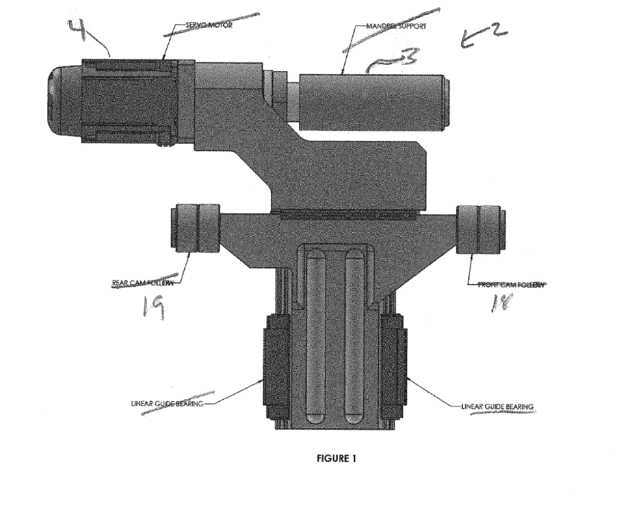
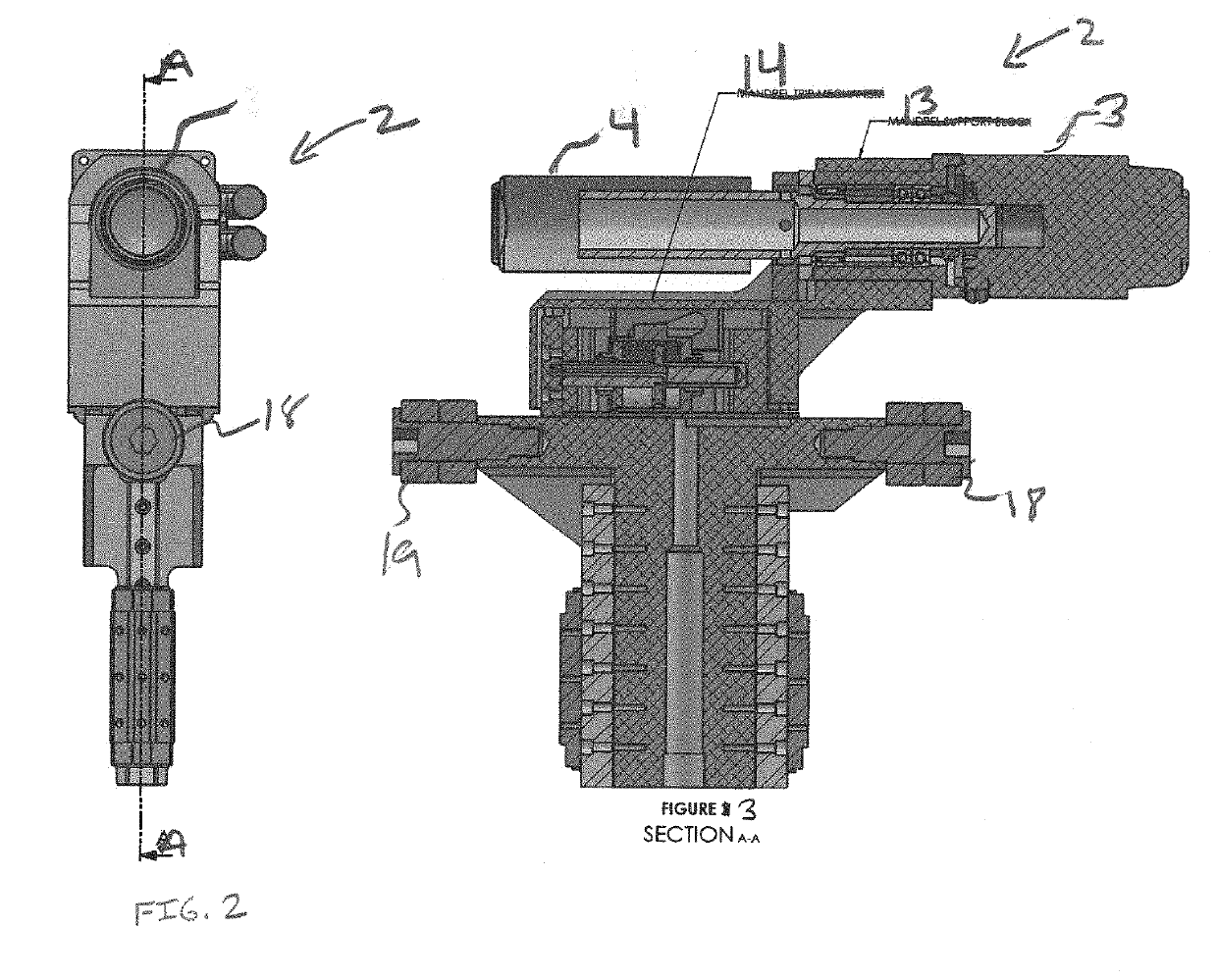
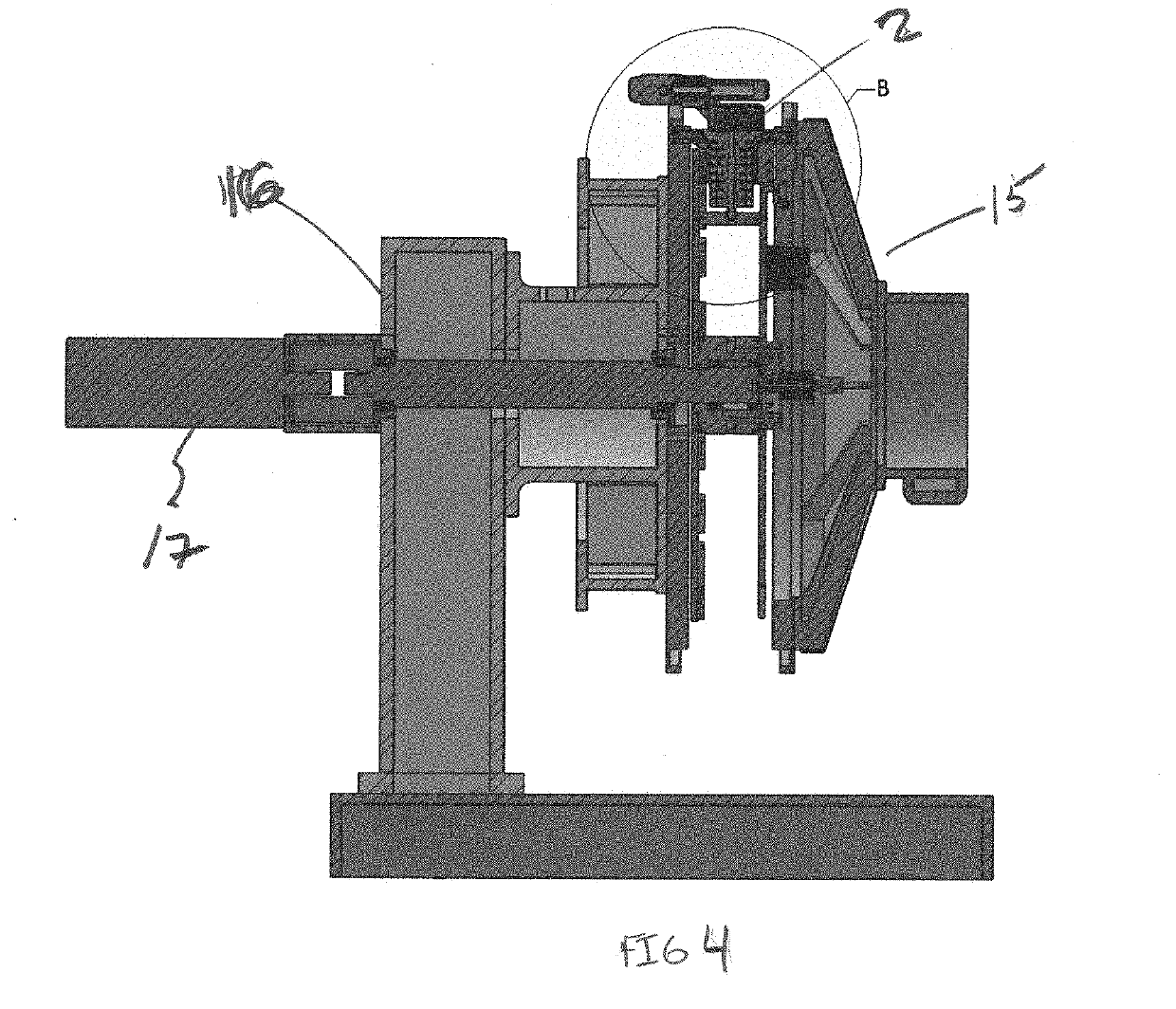
[0024]For purposes of describing the preferred embodiment, the terminology used in reference to the numbered accessories in the drawings is as follows:[0025]1. digital cylinder printing system, generally[0026]2. rail guide mounting assembly[0027]3. mandrel[0028]4. mandrel servo motor[0029]5. color station[0030]6. white color station[0031]7. cyan color station[0032]8. magenta color station[0033]9. yellow color station[0034]10. black color station[0035]11. spot station[0036]12. clear station[0037]13. mandrel support block[0038]14. mandrel trip mechanism[0039]15. disc assembly[0040]16. main shaft assembly[0041]17. support shaft servo motor[0042]18. front cam follower[0043]19. rear cam follower[0044]20. front cam track[0045]21. rear cam track[0046]22. support frame[0047]23. blanket roller[0048]24. transfer roller[0049]25. metering roller[0050]26. doctor roller

[0051]The digital cylinder printing system 1 of the present invention comprises a continuous motion container handler to move eac...


PUM


Abstract

A digital printing system (1) that eliminates the use of printing plates and specially mixed inks, thereby eliminating lost production time caused by the need to change plates as well as cleaning and resupplying inking systems in conventional systems.

Description

CROSS-REFERENCE TO RELATED APPLICATION[0001]This application claims priority to application No. 62 / 663,375, filed on Apr. 27, 2018, which is currently pending. The patent application identified above is incorporated herein by reference in its entirety to provide continuity of disclosure.FIELD OF THE INVENTION[0002]This invention relates to printing systems for aluminum cans and more particularly a digital cylinder printing system that eliminates the use of printing plates and specially mixed inks.BACKGROUND OF THE INVENTION[0003]Conventional printing systems which use offset printing have been used to decorate cylindrical containers, such as aluminum cans, from the early 1900's. These conventional printing systems have the ability to operate in rugged environments and print large volumes of containers extremely quickly. However, conventional printing systems require large amounts of time to change decoration images and inks for new labels, thereby resulting in machine down time duri...

Claims


Application Information

Patent Timeline
IPC IPC(8): B41J3/407B41J2/325
CPCB41J3/4073B41P2219/43B41J2/325B41F17/20B41J3/40733
Inventor JETER, JAMES M.
Owner JETER JAMES M
Why Eureka
Try Eureka