
Camera sensor hidden behind luminaire optics

Inactive Publication Date: 2019-10-31
SIGNIFY HOLDING B V
View PDF0 Cites 0 Cited by
  • Summary
  • Abstract
  • Description
  • Claims
  • Application Information

AI Technical Summary

Benefits of technology

This patent proposes a camera system that uses a camera to sense people, but with a fixed focus a few cm in front of the camera to guarantee privacy. The camera is hidden behind a layer or cover with an optical structure that scrambles the image even more to improve sensitivity and count the number of people present and estimate their speed of movement. The system has a relatively high resolution and is cost-effective. The camera includes an lens system that provides a nearsighted sensor array with a sharp focus at distances close to the camera. The sensor array is configured close to or at the image plane to ensure privacy. The optical structure affects incoming radiation and prevents face recognition. The sensor system can be calibrated and self-learning by measuring a signal of a light source in different positions in the space where the sensor unit is installed.

Problems solved by technology

A disadvantage of PIR sensors is the low resolution: a lens array is needed to create a repeating virtual pattern of the small cluster of sensors such that a certain area may be covered.
The lens array design must be specifically tuned to the application height and detection area, otherwise gaps may occur in the virtual sensor array where no movement can be detected or the virtual sensor images overlap, which reduces the sensitivity of the array.
The cost of a high-resolution smartphone camera is already close to the cost of a 4-pixel PIR sensor.
Further, the present solution may have less issues with distances and may have a larger distance range over which the sensor may sense well, whereas prior art sensors may only sense well over a limited range of distances.

Method used


Image

  • Camera sensor hidden behind luminaire optics
  • Camera sensor hidden behind luminaire optics
  • Camera sensor hidden behind luminaire optics

Examples


Embodiment Construction

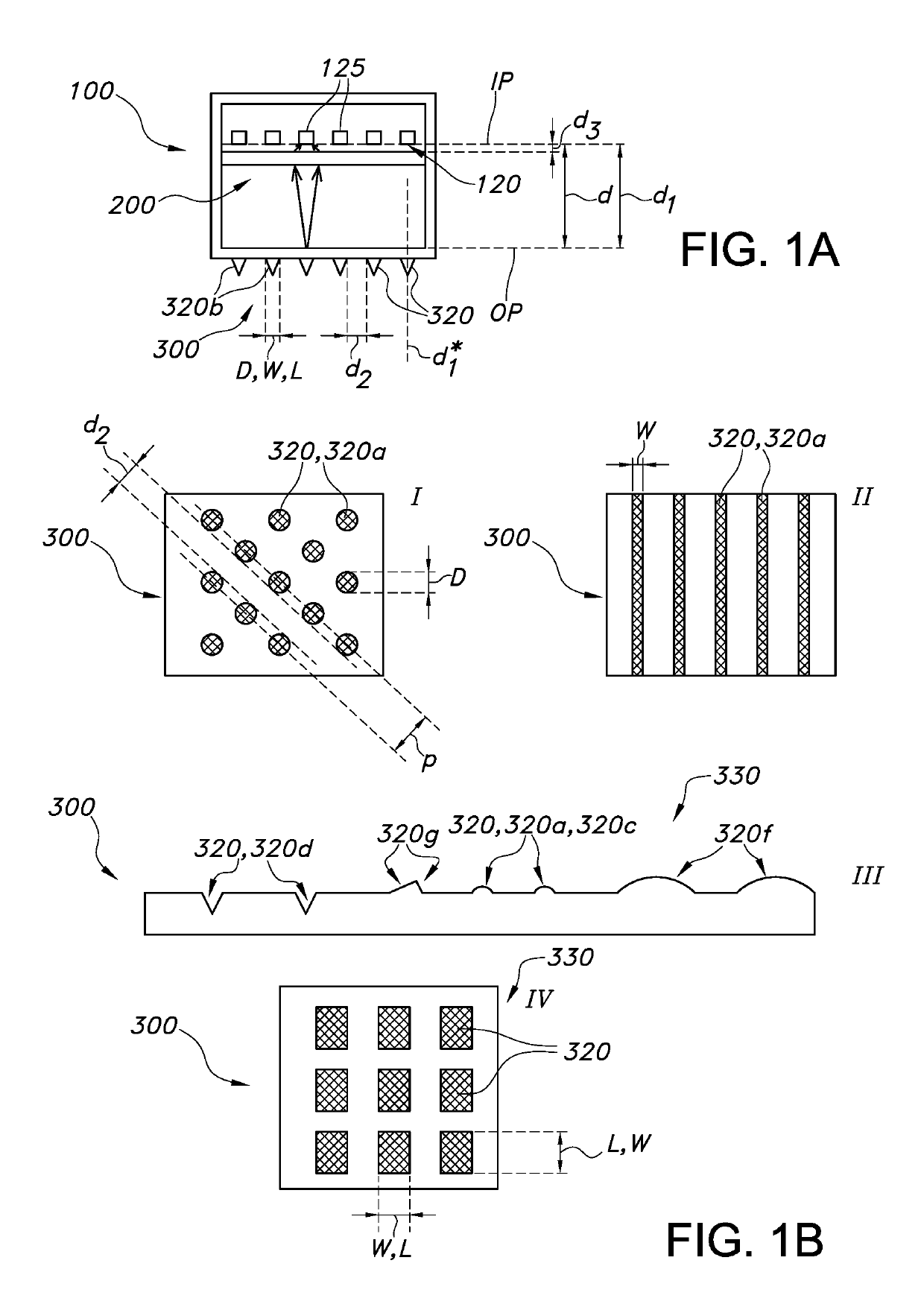
[0054]FIG. 1a schematically depicts an embodiment of a sensor unit 100 comprising a sensor array 120 having at least 100×100 sensor pixels 125, though this is shown in a very simplified version with only 6 pixels by way of example. Further, an optional lens system 200 is schematically depicted. Also an optional light transmissive sensor window 300 comprising optical structures 320 is schematically depicted.

[0055]The light transmissive sensor window 300 is configured at a window distance d from said sensor array 120. The lens system 200 is configured to provide an object-image plane distance d1 selected from the range of 0.1*d-4*d, such as especially 0.9*d-1.1*d. Reference IP indicates the image plane, here coinciding with the 2D sensor array 120, and reference OP indicates the object plane, here by way of example essentially coinciding with the light transmissive sensor window 300. However, the object plane may also be upstream of this window 300 or downstream thereof (but relativel...


PUM


Abstract

The invention provides a sensor unit (100) comprising a sensor array (120) having at least 100×100 sensor pixels (125), a lens system (200), and a light transmissive sensor window (300) comprising optical structures (320), wherein the light transmissive sensor window (300) is configured at a window distance (d) from said sensor array (120), wherein the lens system (200) is configured between the sensor array (120) and said sensor window (300), and wherein an object plane (OP) and an image plane (IP) defined by said lens system (200) and sensor array (120) have an object-image plane distance (d1) selected from the range of 0.1*d-2*d, wherein the optical structures (320) are configured in a pattern, wherein the optical structures (320) have one or more dimensions selected from length (L), width (W) and diameter (D) selected from the range of 50 μm-20 mm, and wherein neighboring optical structures (320) shortest distances (d2) selected from the range of 0-50 mm.

Description

FIELD OF THE INVENTION[0001]The invention relates to a sensor unit and a sensor system comprising such sensor unit. The invention further relates to a lighting system comprising such sensor unit or sensor system. Yet further, the invention also relates to a method of e.g. sensing motion.BACKGROUND OF THE INVENTION[0002]Security cameras in combination with lighting fixtures are known in the art. U.S. Pat. No. 8,622,561 B2, for instance, describes a luminaire, comprising a housing having an outer surface, a cover extending a height above the outer surface, and a camera concealed within the cover. This document also describes a luminaire, comprising a housing made of first and second portions having respective first and second outer surfaces, wherein the first outer surface extends a height substantially above the second outer surface, and a camera concealed within the first portion. Further, this document describes a luminaire, comprising a housing including first and second portions ...

Claims


Application Information

Patent Timeline
IPC IPC(8): F21V33/00G08B15/00G08B13/196F21K9/237H05B37/02
CPCF21K9/237H05B37/0227G08B13/19632F21V33/0076G08B15/001F21K9/272G08B13/193H05B47/125H05B47/13Y02B20/40
Inventor VISSENBERG, MICHEL CORNELIS JOSEPHUS MARIEIJZERMAN, WILLEM LUBERTUS
Owner SIGNIFY HOLDING B V
Learn More