Curved surface generation device and curved surface generation program

Active Publication Date: 2019-10-31
BIPROGY INC +1
View PDF0 Cites 3 Cited by
  • Summary
  • Abstract
  • Description
  • Claims
  • Application Information

AI Technical Summary

Benefits of technology

[0015]Using the aforementioned processing according to the invention, in a case where the shape data of the model and the profile curve are set, and the guide line necessary to sweep the profile curve is unknown, a surface corresponding to that obtained by sweeping the set profile curve along the locus of one point on the profile curve corresponding to

Problems solved by technology

However, there is a problem that it is difficult to correctly specify the guide line necessary for sweeping the profile curve from the measurement data.
However, a method of calculating an appropriate guide line ha

Method used


Image

  • Curved surface generation device and curved surface generation program
  • Curved surface generation device and curved surface generation program
  • Curved surface generation device and curved surface generation program

Examples


first embodiment

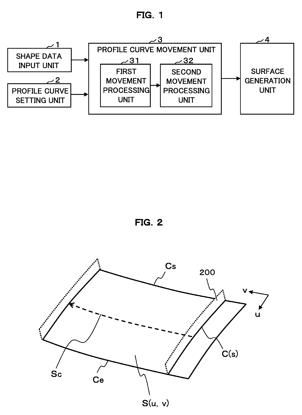
[0021]A first embodiment of the invention will now be described with reference to the accompanying drawings. FIG. 1 is a block diagram illustrating an exemplary functional configuration of a surface generation device according to the first embodiment. As illustrated in FIG. 1, a functional configuration of the surface generation device according to the first embodiment includes a shape data input unit 1, a profile curve setting unit 2, a profile curve movement unit 3, and a surface generation unit 4. The profile curve movement unit 3 has a first movement processing unit 31 and a second movement processing unit 32.

[0022]Each functional block 1 to 4 described above may be configured by any one of hardware, a digital signal processor (DSP), and software. For example, in the case of software, each functional block 1 to 4 described above includes a central processing unit (CPU), a random access memory (RAM), a read-only memory (ROM), or the like of a computer in practice, and is implemen...

second embodiment

[0062]Next, a second embodiment according to the invention will be described with reference to the accompanying drawings. FIG. 5 is a block diagram illustrating an exemplary functional configuration of a surface generation device according to the second embodiment. Note that, in FIG. 5, like reference numerals denote like elements as in FIG. 1, and they will not be described here repeatedly. The surface generation device according to the second embodiment has a second movement processing unit 32′ instead of the second movement processing unit 32.

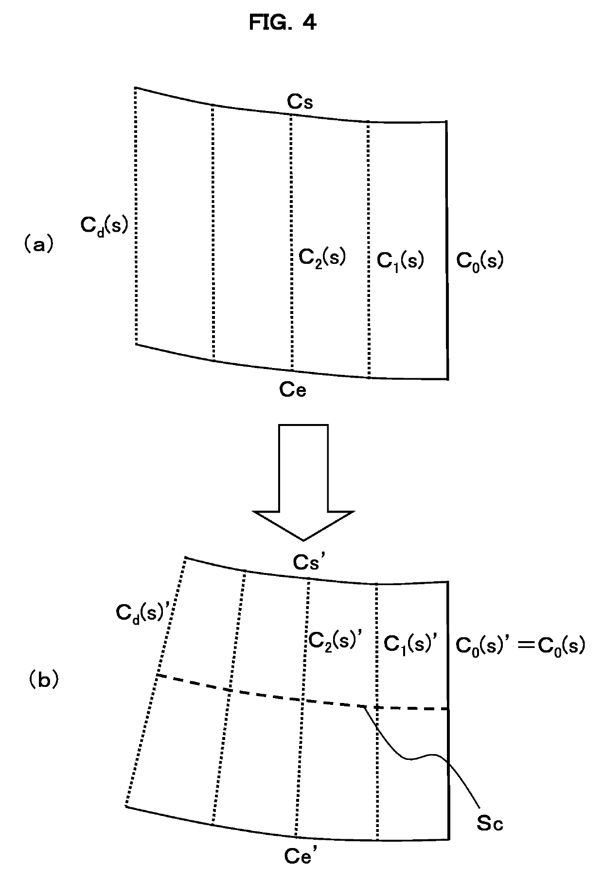
[0063]In the first embodiment described above, an example in which the positions of each profile curve Ci(s)′ are adjusted to satisfy the first condition such that the locus of the point Ci(s*)′ on each profile curve Ci(s)′ formed by moving the profile curve C(s) becomes a line of curvature having a small torsion on the target surface S(u, v) in order to improve the quality of the target surface S(u, v) to be reconstructed from the shape dat...


PUM


Abstract

A surface generation device includes: a profile curve setting unit 2 configured to set a profile curve fitted to a part of shape data, a profile curve movement unit 3 configured to move the profile curve so as to satisfy a predetermined condition, and a surface generation unit 4 configured to generate a surface defined by a locus obtained by moving the profile curve satisfying the predetermined conditions. The predetermined conditions include a condition in which a locus of one point (for example, midpoint) on the profile curve becomes a line of curvature of the surface to be generated. Using such a condition, it is possible to efficiently obtain the high quality surface by setting the line of curvature indicating a flow of the surface as a guide line of a sweep method without repeating trial and error many times.

Description

TECHNICAL FIELD[0001]The present invention relates to a surface generation device and a surface generation program, and more particularly, a surface generation device for generating a surface of a smooth change in curvature desirable in the field of design.BACKGROUND ART[0002]In general, in order to design a product, computer aided design (CAD) is used to generate shape data of the product. As a method of generating the shape data, a method of reconstructing a surface model of an object using CAD from measurement data of the object as a model is widely employed. For example, in the case of a surface shape of an automobile, CAD data are generated from measurement data of a clay model modeled by a clay modeler using a clay spatula (curve ruler).[0003]In order to reconstruct the surface model from the measurement data using a CAD system, it is required that: (i) the generated surface can sufficiently approximate the measurement data within a specified tolerance, and (ii) the generated ...

Claims


Application Information

Patent Timeline
IPC IPC(8): G06T17/30
CPCG06T17/30G06F17/50G06F30/10G06F30/12G06F30/00
Inventor TSUCHIE, SHOICHIMAEKAWA, TAKASHI
Owner BIPROGY INC
Why Eureka
Try Eureka