Magnetic domain wall displacement type magnetic recording element and magnetic recording array
- Summary
- Abstract
- Description
- Claims
- Application Information
AI Technical Summary
Benefits of technology
Problems solved by technology
Method used
Image

Examples
first embodiment
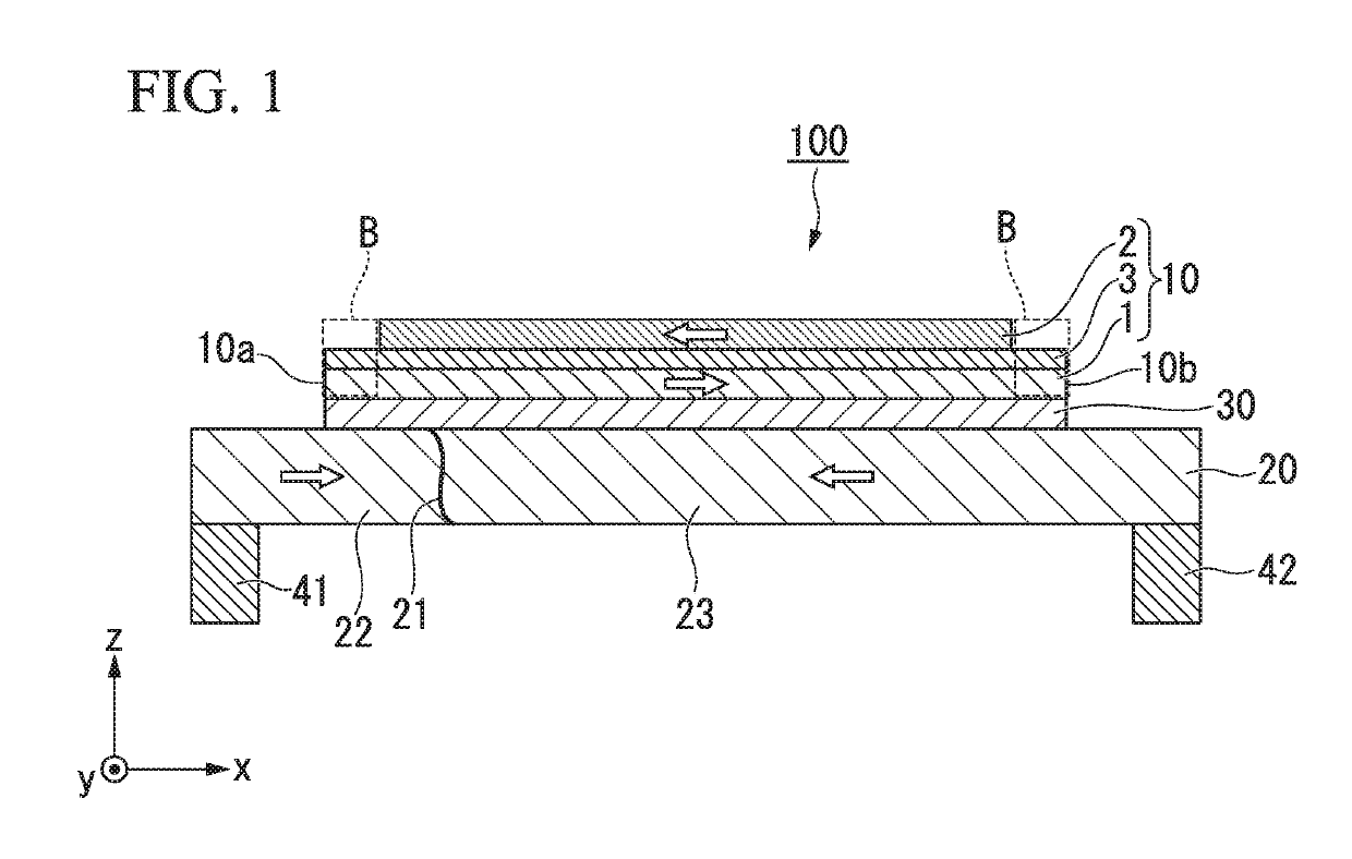
[0037]FIG. 1 is a cross-sectional view schematically showing a magnetic domain wall displacement type magnetic recording element 100 according to a first embodiment. The magnetic domain wall displacement type magnetic recording element 100 includes a first ferromagnetic layer 10, a magnetic recording layer 20, and a nonmagnetic layer 30. The magnetic domain wall displacement type magnetic recording element 100 shown in FIG. 1 includes a first via wiring 41 and a second via wiring 42 at positions between which the first ferromagnetic layer 10 is sandwiched in a plan view.
[0038]Hereinafter, a first direction in which the magnetic recording layer 20 extends is referred to as an x direction, a second direction orthogonal to the x direction within a plane in which the magnetic recording layer 20 extends is referred to as a y direction, and a direction orthogonal to the x direction and the y direction is referred to as a z direction. A laminating direction of the magnetic domain wall disp...
second embodiment
[0082]FIG. 7 is a schematic sectional view of a magnetic domain wall displacement type magnetic recording element 105 according to a second embodiment. The magnetic domain wall displacement type magnetic recording element 105 shown in FIG. 7 is different from the magnetic domain wall displacement type magnetic recording element 100 shown in FIG. 1 in a constitution of a first ferromagnetic layer 11. Other constitutions are the same as those of the magnetic domain wall displacement type magnetic recording element 100 shown in FIG. 1, and the same components are designated by the same reference numerals.
[0083]The first ferromagnetic layer 11 shown in FIG. 7 has a main region 11A located at a center of the first ferromagnetic layer 10 in the x direction, and an end region 11B located at an end thereof. The end region 11B and the main region 11A are formed of different materials. Therefore, the intensity of the magnetic field generated in the main region 11A is different from the intens...
third embodiment
[0089]FIG. 9 is a schematic cross-sectional view of a magnetic domain wall displacement type magnetic recording element 107 according to a third embodiment. The magnetic domain wall displacement type magnetic recording element 107 shown in FIG. 9 is different from the magnetic domain wall displacement type magnetic recording element 100 according to the first embodiment in that a second ferromagnetic layer 50 is provided between the magnetic recording layer 20 and the nonmagnetic layer 30. Components similar to those of the magnetic domain wall displacement type magnetic recording element 100 according to the first embodiment are designated by the same reference numerals, and a description thereof will be omitted.
[0090]Here, an example in which the second ferromagnetic layer 50 is provided between the magnetic recording layer 20 and the nonmagnetic layer 30 of the magnetic domain wall displacement type magnetic recording element 100 will be described as a basic example. However, the...
PUM
 Abstract
Description
Claims
Application Information
 - R&D
- Intellectual Property
- Life Sciences
- Materials
- Tech Scout
- Unparalleled Data Quality
- Higher Quality Content
- 60% Fewer Hallucinations
Browse by: Latest US Patents, China's latest patents, Technical Efficacy Thesaurus, Application Domain, Technology Topic, Popular Technical Reports.
© 2025 PatSnap. All rights reserved.Legal|Privacy policy|Modern Slavery Act Transparency Statement|Sitemap|About US| Contact US: help@patsnap.com