Clock data recovery device

Active Publication Date: 2019-10-31
REALTEK SEMICON CORP
View PDF0 Cites 2 Cited by
  • Summary
  • Abstract
  • Description
  • Claims
  • Application Information

AI Technical Summary

Benefits of technology

[0004]An object of the present invention is to provide a clock data rec

Problems solved by technology

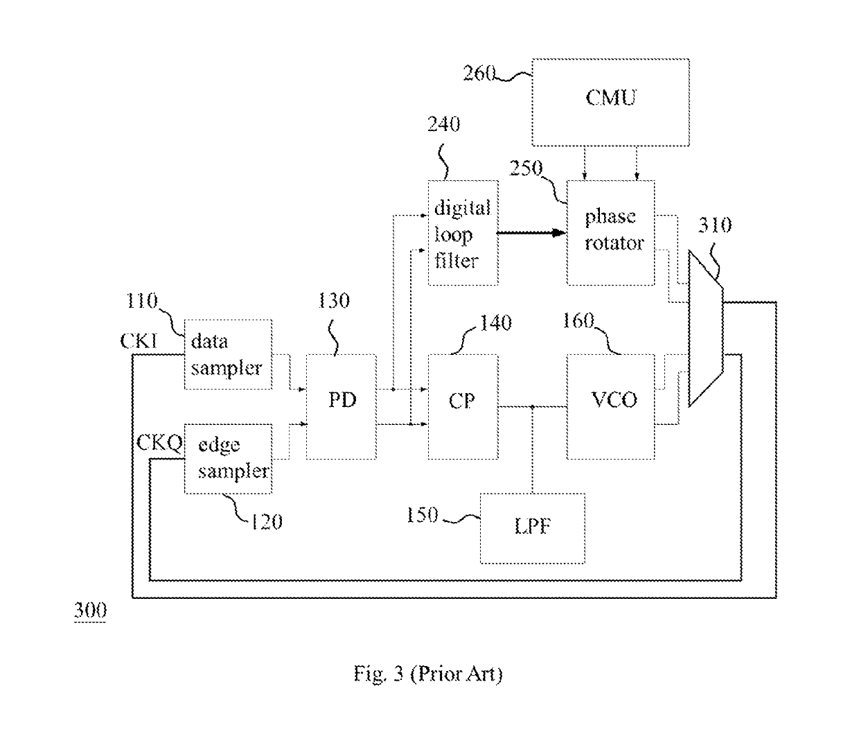
Obviously, many circuits in the combined CDR device 300 are duplicate/similar, and this leads to the increase of circuit area and the waste of cost.
In addition, regarding a multilane application, each lane needs a CDR circuit and if the C

Method used


Image

  • Clock data recovery device
  • Clock data recovery device
  • Clock data recovery device

Examples


Example

[0016]The present invention includes a clock data recovery device capable of operating in one of multiple modes with a compact configuration. Therefore, the present invention is favorable for circuit miniaturization and cost-saving.

[0017]FIG. 4 shows an embodiment of the clock data recovery (CDR) device of the present invention. The CDR device 400 of FIG. 4 includes a master lane circuit 410 and a plurality of slave lane circuits 420 (e.g., three slave lane circuits 420), in which the master lane circuit 410 is coupled to a master lane signal input terminal and outputs an output clock CLKVCO to each slave lane circuit 420 (e.g., outputting the output clock CLKVCO to the phase rotator 840 and the slave lane multiplexer 850 of each slave lane circuit 420 of FIG. 8) while each slave lane circuit 420 is coupled to a slave lane signal input terminal and outputs a phase detection signal SPD (e.g., the phase detection signal outputted by the slave lane phase detector 820 of FIG. 8) to the ...


PUM


Abstract

Disclosed is a clock data recovery (CDR) device including a master lane circuit and a plurality of slave lane circuits. The master lane circuit includes: a clock multiplication unit including a phase frequency detector (PFD), a charge pump (CP), a voltage-controlled oscillator (VCO), and a loop divider; a master lane sampling circuit; a master lane phase detector (PD); and a master lane multiplexer coupled between the master lane PD and the CP and between the PFD and the CP. Each slave lane circuit includes: a slave lane sampling circuit (SLS); a slave lane PD; a slave lane digital loop filter; a phase rotator (PR); and a slave lane multiplexer coupled between the VCO and the SLS and between the PR and the SLS, in which the master lane multiplexer and the slave lane multiplexers are configured to have the CDR device operate in one of multiple modes.

Description

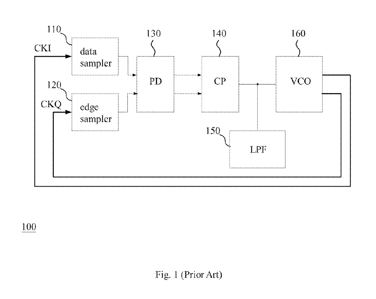
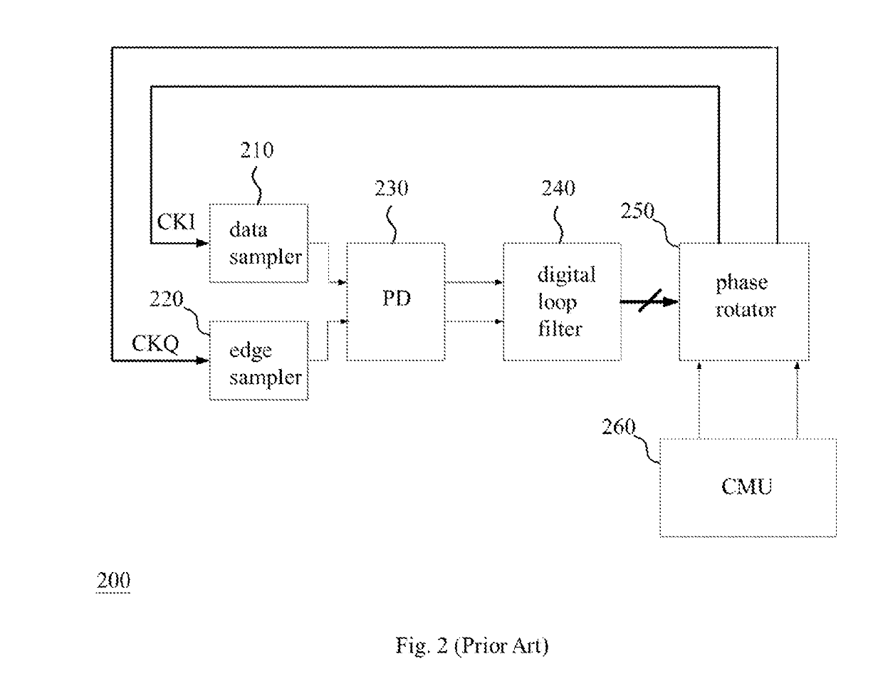
BACKGROUND OF THE INVENTION1. Field of the Invention[0001]The present invention relates to a clock data recovery device, especially to a clock data recovery device capable of operating in one of multiple modes with a compact configuration.2. Description of Related Art[0002]The types of a conventional clock data recovery (CDR) device includes an analog CDR device, a digital CDR device and a combined CDR device composed of an analog CDR device and a digital CDR device. As shown in FIG. 1, a general analog CDR device 100 includes a data sampler (DS) 110, an edge sampler (ES) 120, a phase detector (PD) 130, a charge pump (CP) 140, a low pass filter (LPF) 150 and a voltage-controlled oscillator (VCO) 160 outputting an in-phase clock CM and a quadrature-phase clock CKQ to the data sampler 110 and the edge sampler 120 respectively. As shown in FIG. 2, a general digital CDR device 200 includes a data sampler 210, an edge sampler 220, a phase detector 230, a digital loop filter (DLF) 240, a ...

Claims


Application Information

Patent Timeline
IPC IPC(8): H04L7/033H03L7/08H03L7/087H03L7/099
CPCH03L7/0807H03L7/087H03L7/099H04L7/0332H04L7/0331H03L7/0992H04L7/033H03L7/0814H03L7/07
Inventor LIU, JIANKUAN, CHI-KUNG
Owner REALTEK SEMICON CORP
Why Eureka
Try Eureka