Edge-Missing Detector Structure

Inactive Publication Date: 2010-11-04
NAT APPLIED RES LAB NAT CHIP IMPLEMENTATION CENT
View PDF8 Cites 4 Cited by
  • Summary
  • Abstract
  • Description
  • Claims
  • Application Information

AI Technical Summary

Benefits of technology

[0016]1. The edge-missing detector structure is configured for accurately detecting the number of occurrences of edge-missing in input signals, thus preventing the cycle slip problems.
[0017]2. By preventing the cycle slip problems, the acquisition time of a phase-locked loop using the edge-missing detector structure is shortened.
[0018]3. The edge-missing detector str

Problems solved by technology

In practice, however, the ideal phase detector has never been realized.
As mentioned earlier, the ideal linear phase detector cannot be actually made.
However, the subject matter of the aforesaid US patent

Method used


Image

  • Edge-Missing Detector Structure
  • Edge-Missing Detector Structure
  • Edge-Missing Detector Structure

Examples


Example

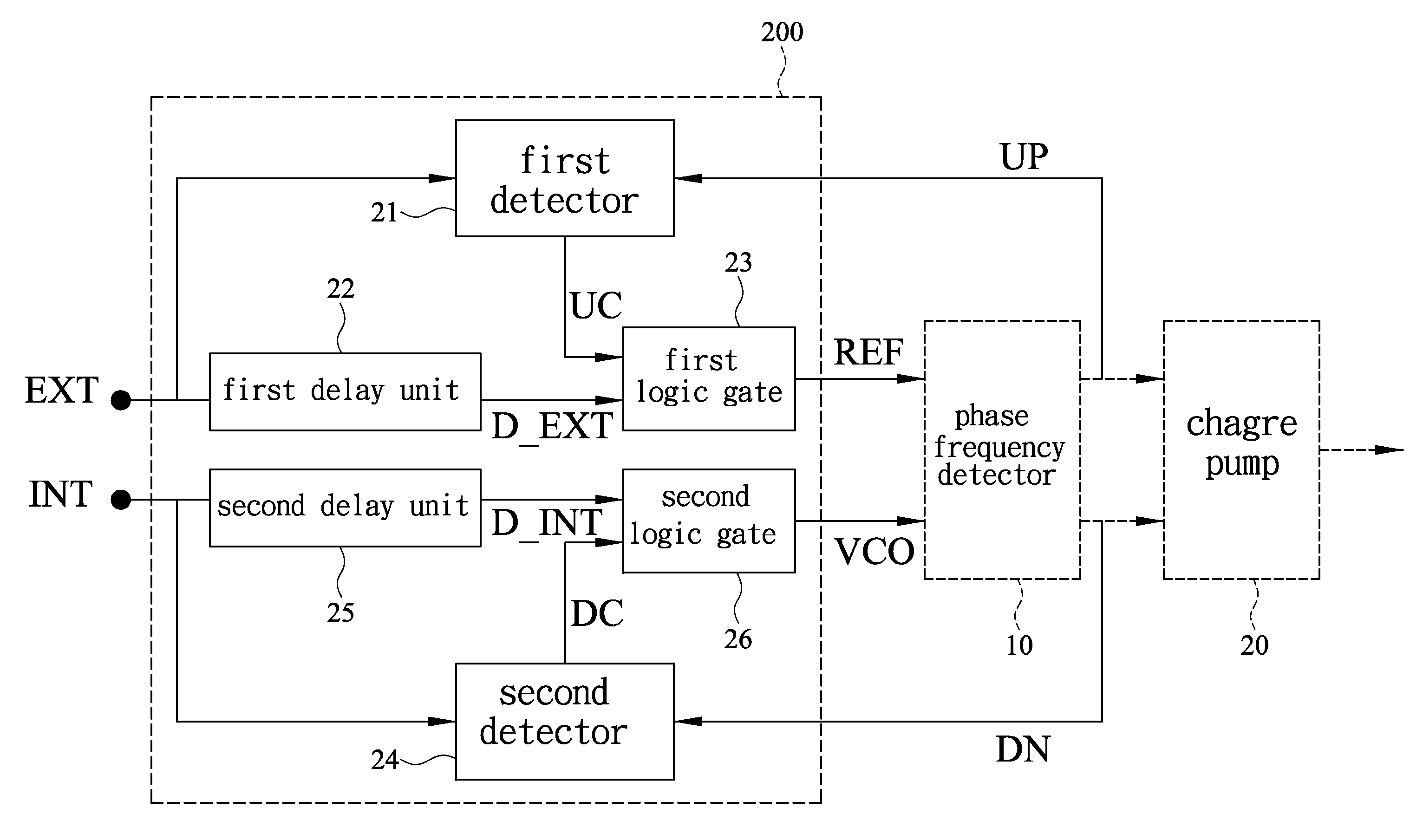
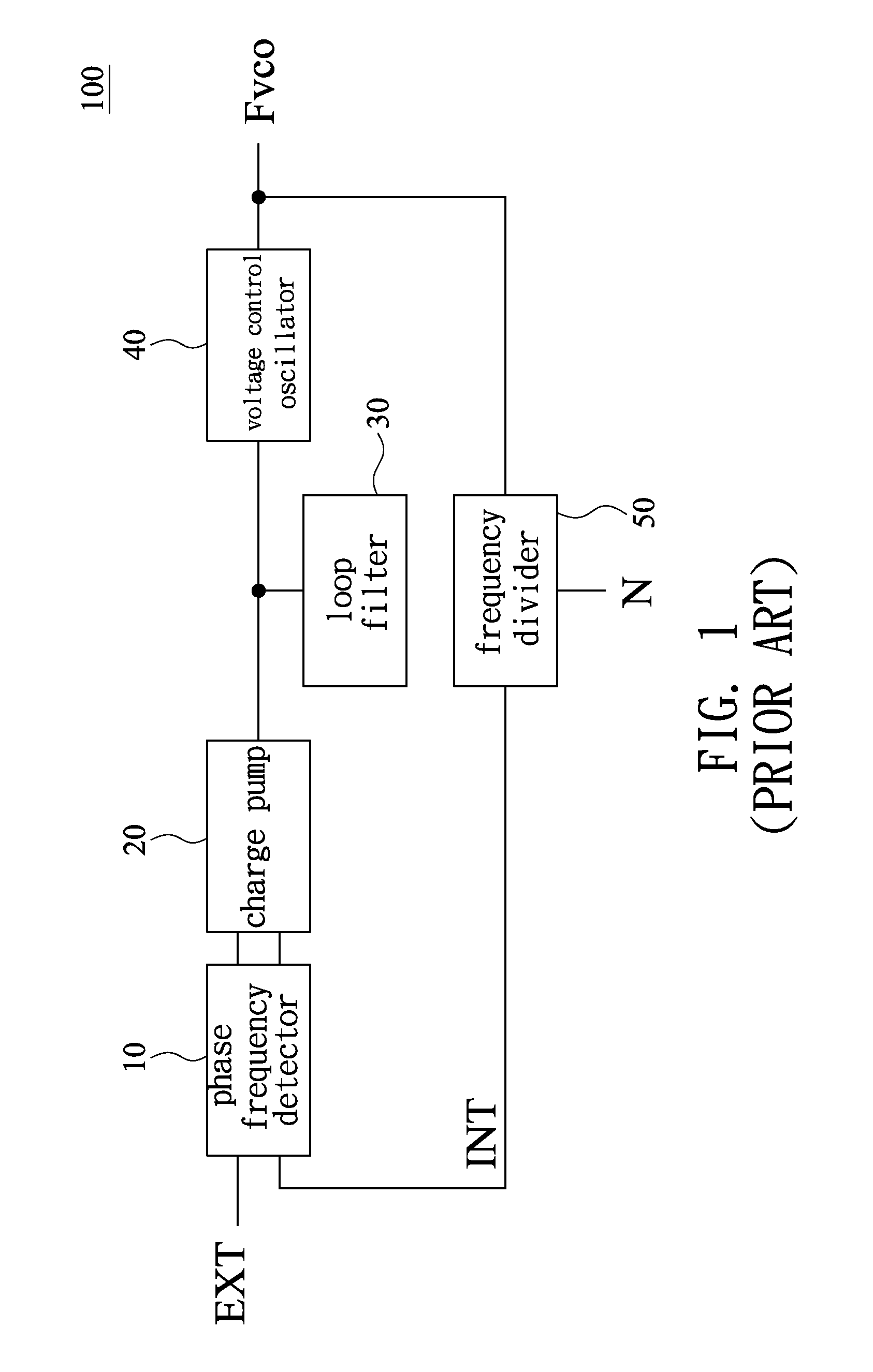
[0029]Referring to FIG. 4 and FIG. 5, an edge-missing detector structure 200 according to an embodiment of the present invention includes a first detector 21, a first delay unit 22, a first logic gate 23, a second detector 24, a second delay unit 25, and a second logic gate 26. As shown in FIG. 4, the edge-missing detector structure 200 is used in a phase-locked loop (PLL) 100′ and coupled with a signal input end of a phase frequency detector 10. Therefore, as shown in FIG. 5, a first reference signal EXT and a first clock signal INT are processed by the edge-missing detector structure 200 before being input to the phase frequency detector 10.

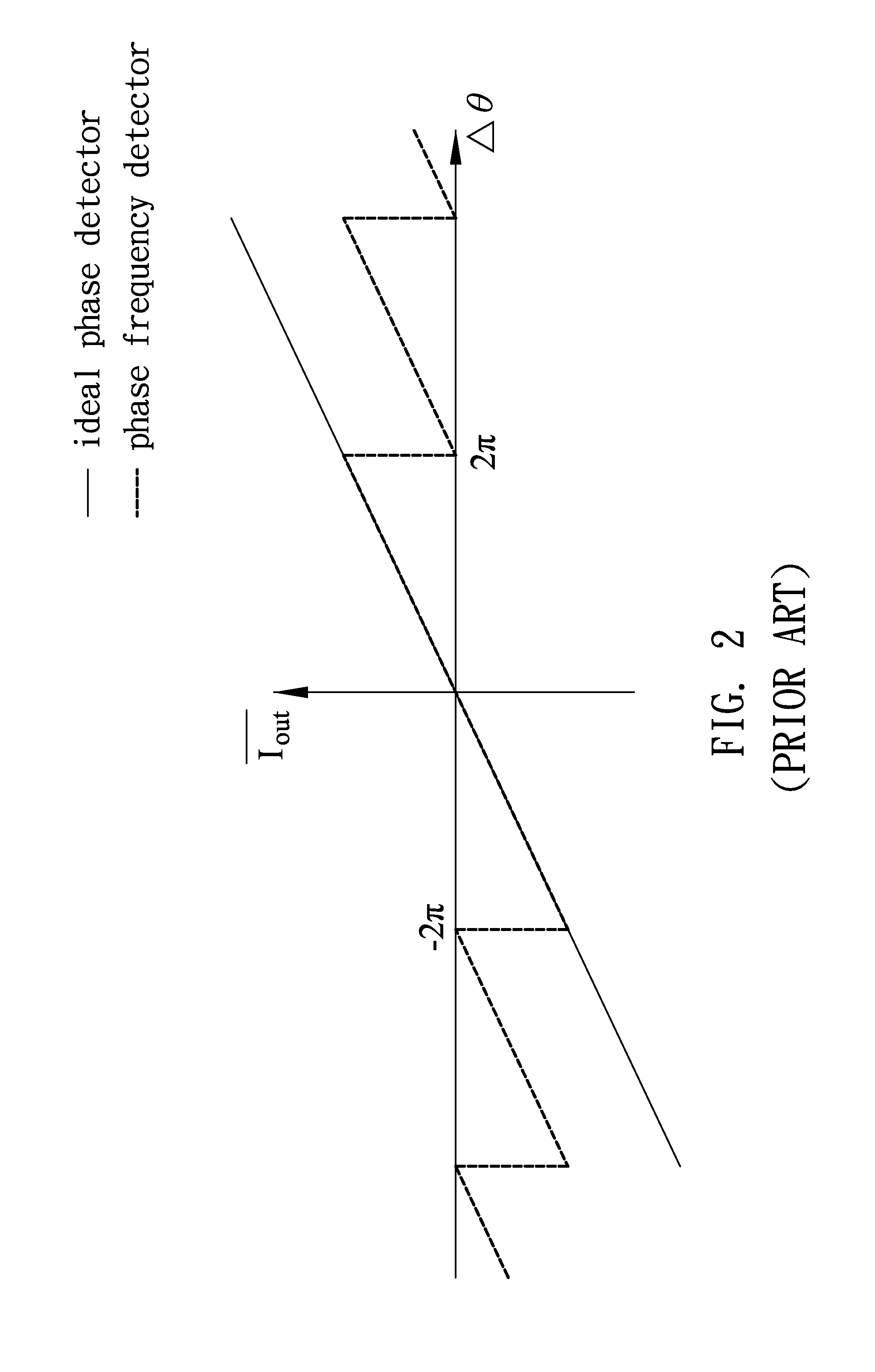
[0030]When the signals input to the phase frequency detector 10 present a phase difference Δθ close to or greater than 2π, the phase frequency detector 10 generates from an output end thereof a first enable signal UP or a third enable signal DN, depending on whether the phase difference Δθ is a positive phase difference or a negative phase diff...


PUM


Abstract

An edge-missing detector structure includes a first detector, a first delay unit, a first logic gate, a second detector, a second delay unit, and a second logic gate. After being input separately into the edge-missing detector structure, a first reference signal and a first clock signal are detected by the first and second detectors and then subjected to cycle suppression by the first and second logic gates, respectively, so as to generate a second reference signal and a second clock signal which present a phase difference less than 2π. Moreover, the edge-missing detector structure generates a compensative current corresponding to the number of occurrences of cycle suppression. Thus, a phase-locked loop (PLL) using the edge-missing detector structure can avoid cycle slip problems and achieve fast acquisition of phase lock.

Description

BACKGROUND OF THE INVENTION[0001]1. Technical Field[0002]The present invention relates to edge-missing detector structures and, more particularly, to an edge-missing detector structure for use in a phase-locked loop (PLL).[0003]2. Description of Related Art[0004]A phase-locked loop is a circuit structure used extensively in a variety of communication-related devices such as clock / frequency generators, wireless receivers, and telecommunication equipment. With the advancement of technology, phase-locked loops have found applications in systems beyond the field of communication devices. For example, phase-locked loops are now also used in data recovery circuits, frequency synthesizers, and so on.[0005]FIG. 1 is a circuit diagram of a conventional phase-locked loop 100. FIG. 2 is a graph showing characteristic curves of a conventional phase frequency detector 10 and an ideal phase detector. FIG. 3 is a graph showing the comparison of acquisition time between ideal phase detector and con...

Claims


Application Information

Patent Timeline
IPC IPC(8): H03K5/19
CPCH03K5/1534H03L7/10H03L7/0891H03K5/19
Inventor CHIEN, TING HSULIN, CHI SHENGWEY, CHIN-LONGHUANG, CHUN-MINGJUANG, YING-ZONG
Owner NAT APPLIED RES LAB NAT CHIP IMPLEMENTATION CENT
Why Eureka
Try Eureka