Metal halide lamp

Inactive Publication Date: 2006-06-13
PANASONIC CORP
View PDF45 Cites 3 Cited by
  • Summary
  • Abstract
  • Description
  • Claims
  • Application Information

AI Technical Summary

Benefits of technology

[0006]The above-described problems occur since the filled cerium halide reacts with the ceramic material, resulting in a drastic reduction of cerium halide that serves for light emission.
[0007]For preventing the problems, a metal halide lamp according to the present invention comprises an

Problems solved by technology

The above-described problems occur since the filled cerium halide reacts with the ceramic

Method used


Image

  • Metal halide lamp
  • Metal halide lamp
  • Metal halide lamp

Examples


Example

EXAMPLE 1

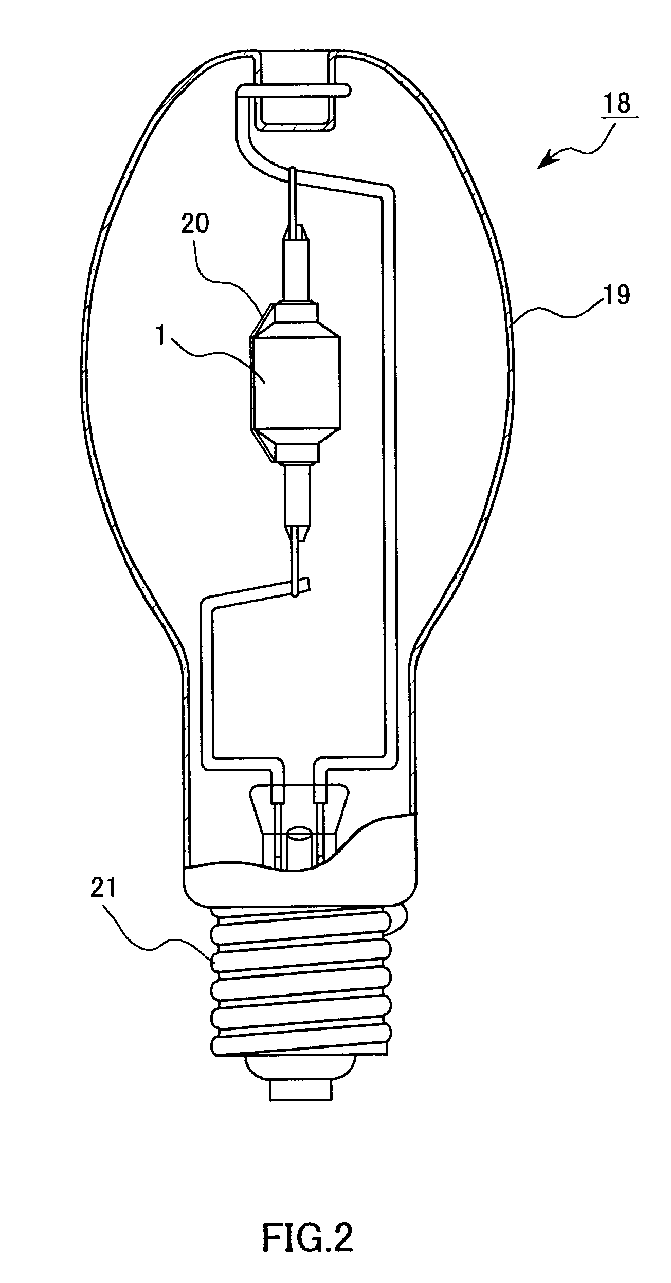
[0025]For examining the service life in aging, a lamp 18 comprising an arc tube 1 was prepared. The arc tube 1 was previously filled with 6 mg of a luminescent material 17 composed of 35 wt % (14 mol %) of CeI3, 60 wt % (83.5 mol %) of NaI, and 5 wt % (2.5 mol %) of ScI3. As shown in FIG. 3 as a line of Ce / Sc / Na, the flux maintenance factor of the lamp was improved drastically to 65% when the aging time was about 12000 hrs. The color temperature change during the aging was not more than −150 K, and this was better in comparison with a lamp that was not filled with ScI3.

[0026]In an analysis of the lamp after an aging of 5000 hrs, a sufficient amount of CeI3 remained (80–90% of the initial filling amount). To the contrary, only 20–30% of ScI3 remained since relatively a large amount of ScI3 reacted with the alumina ceramic.

[0027]Among the initial properties of the lamp 18, the flux and the luminous efficiency were 22800 lm and 117 lm / W respectively i.e., initial values thereo...

Example

COMPARATIVE EXAMPLE 1

[0028]A lamp 18 comprising a conventional arc tube 1 was prepared. The lamp 18 was filled with 6 mg of a luminescent material 17 composed of cerium-sodium iodides (36 wt % (13.9 mol %) of CeI3+64 wt % (86.1 mol %) of NaI). This NaI / CeI3 composition ratio according to the conventional technique provides a white light source color in a range from about 3500 K to about 4000 K,

[0029]First, the initial properties of the lamp were measured at an aging time of 100 hrs. For a white light source color having a color temperature of 4100 K the lamp flux was 23600 lm and the luminous efficiency was 118 lm / W (both are average values of four lamps). Namely, a desired value (117 ml / W) of luminous efficiency was obtained barely, though the general color rendering index was 60, i.e., lower than the desired value of 65.

[0030]Next, a lamp aging test was carried out for measuring the flux maintenance factor. As illustrated by the line of Ce / Na in FIG. 3, the flux maintenance factor...

Example

EXAMPLE 2

[0034]A lamp was prepared under the same condition of Example 1 except that the filling amount of scandium iodide was varied in a range from 0 to 200 molar parts with respect to 100 molar parts of CeI3, and the lamp was subjected to an aging test. When the amount of the scandium iodide exceeded 100 molar parts, the tungsten electrodes (6,7) were deformed and worn and also the arc tube was blackened, and this caused lowering of the flux maintenance factor. When the amount of the scandium iodide was less than 1.5 molar parts, no specific effects were expressed in suppressing a reaction between alumina and cerium halide.

[0035]The test results show that a preferred range of the amount of scandium iodide is from 1.5 molar parts to 100 molar parts when CeI3 is 100 molar parts. In an analysis after the aging, a small amount of aluminum was detected in the tube of a lamp in which at least 150 molar parts of ScI3 had been filled. The aluminum is derived from aluminum iodide (AlI3), ...


PUM


Abstract

A metal halide lamp has an arc tube including an arc tube container made of an oxide-based translucent ceramic material. The arc tube is filled with cerium halide as a luminescent material and a halide of a rare earth element that is more reactive with the ceramic material than is the cerium halide. Accordingly, a reaction between the oxide-based translucent ceramic material and the halide of a rare earth element is accelerated while a reaction between the oxide-based translucent ceramic material and the cerium halide is suppressed. This suppresses a decrease of the cerium halide that serves for light emission, and also reduces changes in the lamp color temperature. Thereby, during aging of the lamp, the flux maintenance factor and color temperature are improved. Therefore, the indoor-outdoor metal halide lamp provides a white light source color that has high-wattage, high luminous efficiency, and a long service life.

Description

FIELD OF THE INVENTION[0001]The present invention relates to an arc tube used for a metal halide lamp.BACKGROUND OF THE INVENTION[0002]Metal halide lamps using ceramic arc tubes have been used widely for indoor lighting in stores and shops because such metal halide lamps have higher luminous efficiency, higher color rendering and longer service lives when compared to metal halide lamps using quartz arc tubes.[0003]FIGS. 5 and 6 show respectively a metal halide lamp using a conventional ceramic arc tube. An arc tube 28 comprises an arc tube container 29 composed of a discharge arc tube portion 30 of a polycrystalline alumina ceramic material and a pair of thin tube portions (31, 32) sintered at the both ends of the discharge arc tube portion 30. A pair of tungsten coil electrodes (33, 34) are arranged at the both ends of the arc tube 28. Feeding portions (35, 36) of niobium or conductive cermet are adhered hermetically to the thin tube portions (31, 32) by means of frit 37, and the t...

Claims


Application Information

Patent Timeline
IPC IPC(8): H01J17/20H01J61/12
CPCH01J61/125
Inventor HIGASHI, MASANORINISHIURA, YOSHIHARUODA, SHIGEFUMIENAMI, HIROSHIKAKISAKA, SHUNSUKE
Owner PANASONIC CORP
Why Eureka
Try Eureka