A wave-induced motion compensating crane for use on an offshore vessel, vessel and load transferring method

Active Publication Date: 2019-11-07
ITREC BV
View PDF0 Cites 7 Cited by
  • Summary
  • Abstract
  • Description
  • Claims
  • Application Information

AI Technical Summary

Benefits of technology

[0031]Yet another advantage of the crane according to the first aspect of the invention is that the motion compensation device is capable of carrying a relatively large load.
[0032]In an embodiment, the level setting device is connected to the control unit, wherein the control unit is configured to operate the level setting device at least prior to operating in the wave-induced motion compensation mode to set the pedestal member level in correspondence with the angle of the boom structure portion that carries the motion compensation device. The main advantage thereof is that the linear motion path of the jib beam is substantially horizontal and consequently the slew axis of the jib beam support member is substantially vertical thereby resulting in a substantially optimal uncoupling of the horizontal and vertical motion compensation.
[0033]In an embodiment, the control unit is further configured to keep the pedestal member stationary relative to the boom portion during the wave-induced motion compensation mode. This may reduce the dynamic load requirements for the level setting device thereby increasing the weight of the load that can be carried. Alternatively, e.g. especially for relatively small loads,

Problems solved by technology

When transferring loads from and to a vessel, wave-induced motion of the vessel is a well-known problem to be dealt with during this process.
However, a drawback of such a jack-up type vessel is that it takes a lot of time to lower the legs and to lift the vessel out of the water and to go through the reverse process after transferring the load.
An advantage thereof is that any type of crane can be posit

Method used


Image

  • A wave-induced motion compensating crane for use on an offshore vessel, vessel and load transferring method
  • A wave-induced motion compensating crane for use on an offshore vessel, vessel and load transferring method
  • A wave-induced motion compensating crane for use on an offshore vessel, vessel and load transferring method

Examples


Example

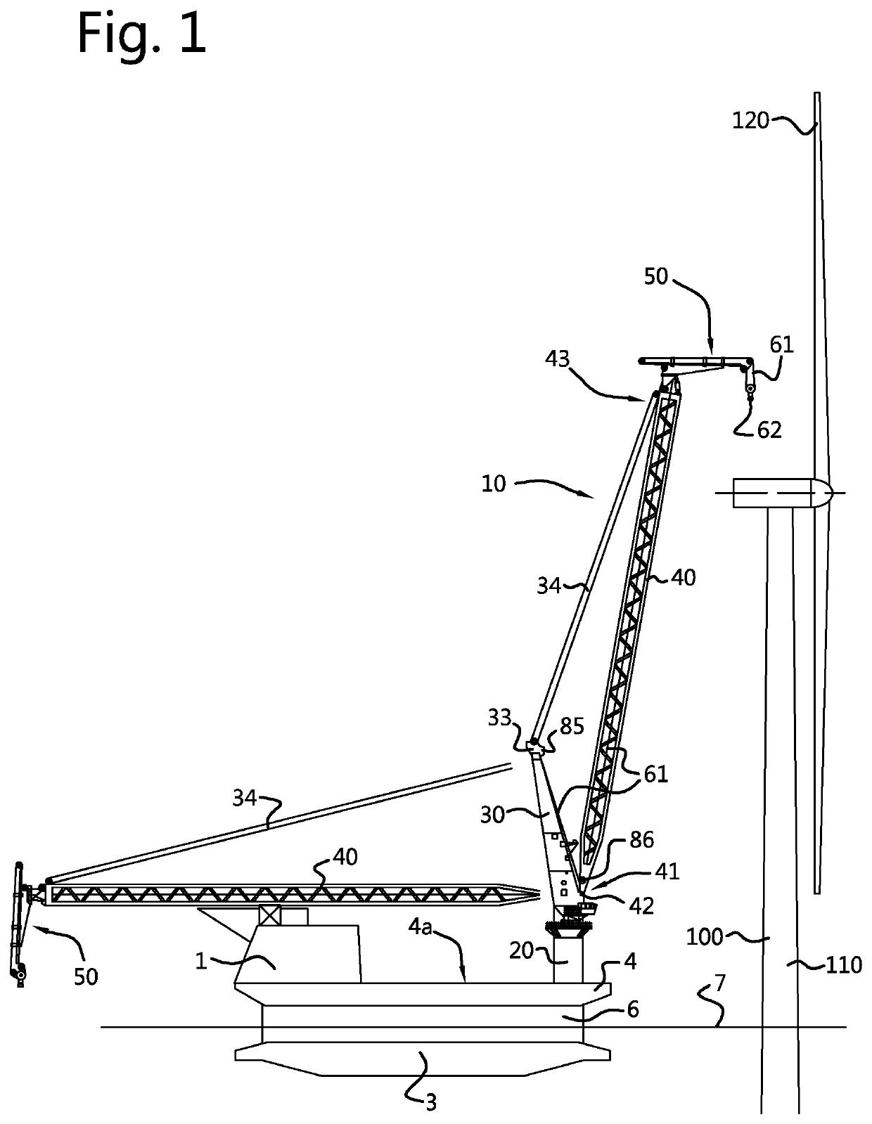
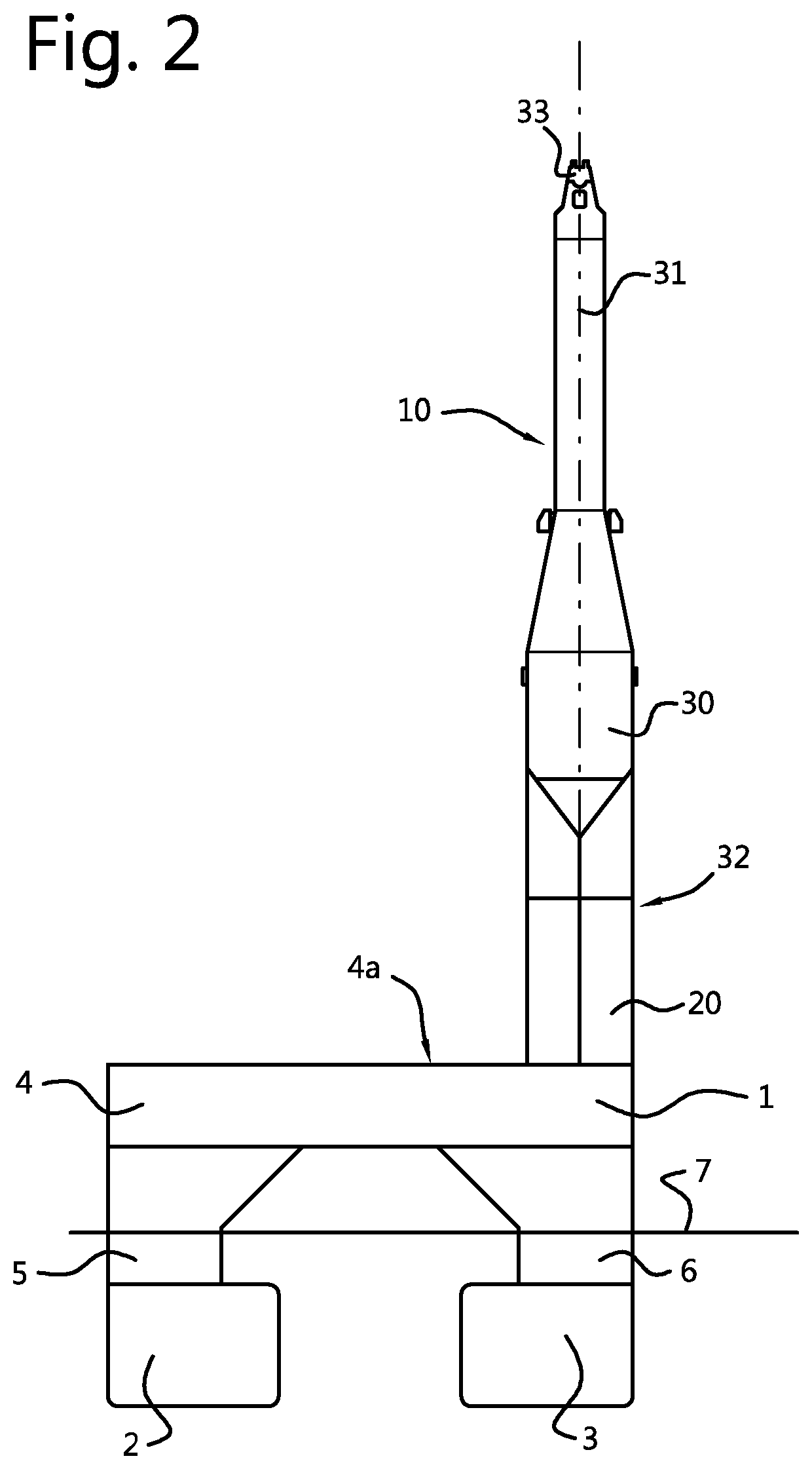
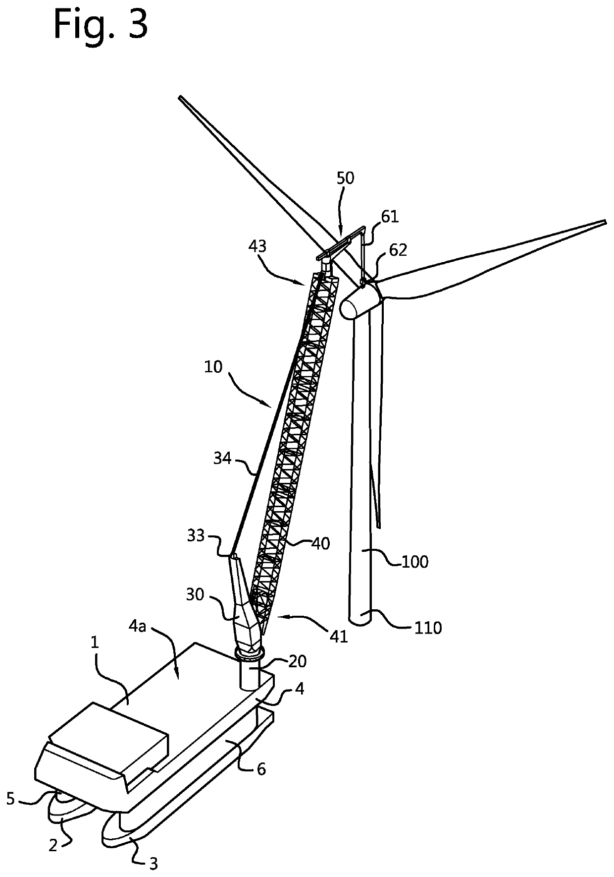
[0123]In FIGS. 1-3 a vessel 1 is schematically depicted. The exemplary vessel 1 comprises two elongated pontoons 2, 3 and a platform or deck box 4 that is supported from the two pontoons 2,3 by two respective columns 5,6. Although a single column per pontoon is depicted in the figures, thereby resulting in a SWATH-type vessel, it will be apparent that other configurations, for instance in which two or three columns per pontoon are provided, thereby resulting in a more conventional semi-submersible vessel, are also feasible and envisaged.

[0124]As mentioned before, the advantage of a SWATH-type or semi-submersible vessel over a conventional monohull vessel is that the total cross sectional area of the columns intersecting the water surface 7 is smaller in a SWATH-type or semisubmersible vessel than the total cross sectional area of a conventional monohull vessel intersecting the water surface, so that the wave-induced motions of such a SWATH-type or semi-submersible vessel are smaller...


PUM


Abstract

A wave-induced motion compensation crane and corresponding vessel and method are disclosed. The crane includes a motion compensation device at a tip end portion of the boom structure to compensate for X-Y wave-induced motion and a heave compensation device for Z-motion. The motion compensation device includes a moveable jib beam that extends in a substantially horizontal direction. The jib beam is slewable about a substantially vertical slew axis and translatable in a longitudinal direction of the jib beam. Preferably, the jib beam can be levelled based on the angular orientation of the boom structure.

Description

FIELD OF THE INVENTION[0001]The invention relates to a wave-induced motion compensating crane for use on an offshore vessel, e.g. for installation or removal of one or more components of an offshore wind turbine. The invention further relates to a vessel comprising such a crane, and to a method to transfer loads using such a crane.BACKGROUND OF THE INVENTION[0002]When transferring loads from and to a vessel, wave-induced motion of the vessel is a well-known problem to be dealt with during this process. A well-known solution to this problem is to make use of a jack-up type of vessel in which legs are lowered into the water to lift the vessel at least partially out of the water so that waves have a limited or minimal effect on the vessel. However, a drawback of such a jack-up type vessel is that it takes a lot of time to lower the legs and to lift the vessel out of the water and to go through the reverse process after transferring the load.[0003]Another prior art solution is to compen...

Claims


Application Information

Patent Timeline
IPC IPC(8): B66C13/04B66C23/52B66D1/50B63B27/10F03D13/10
CPCB66C13/04F03D13/10B66C23/52B63B27/10B66D1/50B66C23/185B66C13/02B66D1/52Y02E10/72
Inventor ROODENBURG, DAVIDVAN VELUW, CORNELIS MARTINUSWIECK, BART OTTO FREDRIKDEN BOER, WOUTER JACOB WILLEM
Owner ITREC BV
Why Eureka
Try Eureka