Memory-based distributed processor architecture

a distributed processor and processor technology, applied in the direction of memory adressing/allocation/relocation, architecture with multiple processing units, instruments, etc., can solve the problems of conventional computer architecture throughput limitations, bottlenecks in effective processing speeds, and bottlenecks in von neumann bottlenecks, and achieve efficient effective processing speeds

Active Publication Date: 2019-11-07
NEUROBLADE LTD
View PDF12 Cites 17 Cited by
  • Summary
  • Abstract
  • Description
  • Claims
  • Application Information

AI Technical Summary

Problems solved by technology

As processor speeds and memory sizes both continue to increase, a significant limitation on effective processing speeds is the von Neumann bottleneck.
The von Neumann bottleneck results from throughput limitations resulting from conventional computer architecture.
In particular, data transfer from memory to the processor is often bottlenecked compared to actual computations undertaken by the processor.
Accordingly, the number of clock cycles to read and write from memory increases significantly with memory-intensive processes.
These clock cycles result in lower effective processing speeds because reading and writing from memory consumes clock cycles that cannot be used for performing operations on data.
However, it has also brought cumbersome challenges to the world of data bases and parallel computing.
However, the new data has been difficult to store, process, analyze and handle.
Moreover, the growth rate of these data resources may exceed data processing capabilities.
But these existing systems and methods have not kept up with the data processing requirements, often because the techniques employed are limited by their demand of additional resources for data management, integration of segregated data, and analysis of the sectioned data.
For instance, if the new chips designed for data intensive tasks are manufactured with fabrication techniques and architectures used for common chips, they would have a poor performance and / or unacceptable yields.
In addition, if the new chips are designed to operate with current data handling methods, they will have poor performance because current methods can limit the chip's ability to handle parallel operations.

Method used


Image

  • Memory-based distributed processor architecture
  • Memory-based distributed processor architecture
  • Memory-based distributed processor architecture

Examples


Embodiment Construction

[0066]The following detailed description refers to the accompanying drawings. Wherever convenient, the same reference numbers are used in the drawings and the following description to refer to the same or similar parts. While several illustrative embodiments are described herein, modifications, adaptations and other implementations are possible. For example, substitutions, additions or modifications may be made to the components illustrated in the drawings, and the illustrative methods described herein may be modified by substituting, reordering, removing, or adding steps to the disclosed methods. Accordingly, the following detailed description is not limited to the disclosed embodiments and examples. Instead, the proper scope is defined by the appended claims.

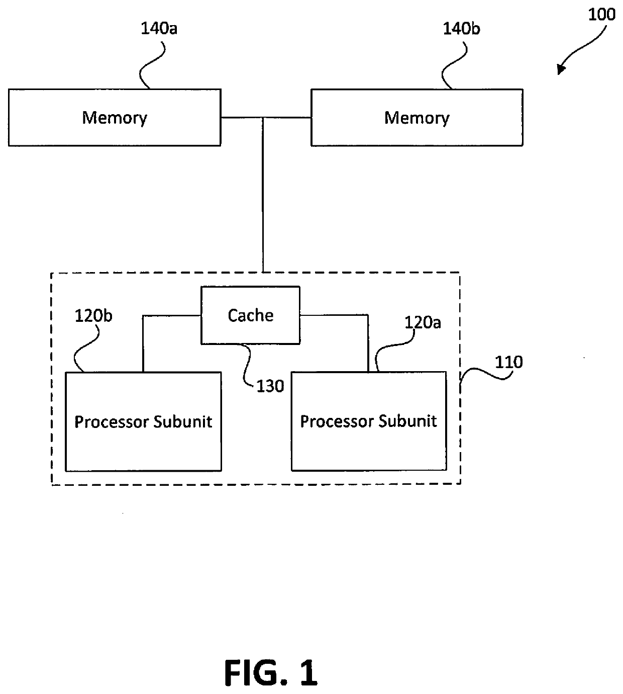
[0067]Processor Architecture

[0068]As used throughout this disclosure, the term “hardware chip” refers to a semiconductor wafer (such as silicon or the like) on which one or more circuit elements (such as transistors, capacitor...


PUM


Abstract

Distributed processors and methods for compiling code for execution by distributed processors are disclosed. In one implementation, a distributed processor may include a substrate; a memory array disposed on the substrate; and a processing array disposed on the substrate. The memory array may include a plurality of discrete memory banks, and the processing array may include a plurality of processor subunits, each one of the processor subunits being associated with a corresponding, dedicated one of the plurality of discrete memory banks. The distributed processor may further include a first plurality of buses, each connecting one of the plurality of processor subunits to its corresponding, dedicated memory bank, and a second plurality of buses, each connecting one of the plurality of processor subunits to another of the plurality of processor subunits.

Description

CROSS REFERENCES TO RELATED APPLICATIONS[0001]This application is a continuation of PCT / IB2018 / 000995, filed on Jul. 30, 2018, which claims the benefit of priority of U.S. Provisional Patent Application No. 62 / 538,722, filed on Jul. 30, 2017, U.S. Provisional Patent Application No. 62 / 538,724, filed on Jul. 30, 2017, and U.S. Provisional Patent Application No. 62 / 548,990, filed on Aug. 23, 2017. All of the foregoing applications are incorporated herein by reference in their entireties.BACKGROUNDTechnical Field[0002]The present disclosure relates generally to apparatuses for facilitating memory-intensive operations. In particular, the present disclosure relates to hardware chips that include processing elements coupled to dedicated memory banks.Background Information[0003]As processor speeds and memory sizes both continue to increase, a significant limitation on effective processing speeds is the von Neumann bottleneck. The von Neumann bottleneck results from throughput limitations r...

Claims


Application Information

Patent Timeline
Patent Type & Authority Applications(United States)
IPC IPC(8): G11C11/16G11C11/4093G06F13/16
CPCG11C11/1675G06F13/1657G11C11/4093G06F12/06G06F8/41G06F8/427G06F8/45G06F9/3889G06F9/3885G06F9/3895G06F15/8038G06F11/1016G06F11/102G06F9/3001G06F2015/765G11C7/1072G11C11/4076G11C11/1657G11C11/1655G11C11/408G06N3/04G06F11/1658G06F11/1616G06F11/16
Inventor SITY, ELADHILLEL, ELIAD
Owner NEUROBLADE LTD
Why Eureka
Try Eureka