Magnetic encoder, and method and device for producing same

a technology of encoder and encoder track, which is applied in the direction of measuring device, magnetic body, instrument, etc., can solve the problem that the encoder track should have a higher accuracy, and achieve the effect of high accuracy, higher accuracy, and unavoidable influence on the accuracy of the already magnetized magnetic track

Inactive Publication Date: 2019-11-14
NTN CORP
View PDF0 Cites 6 Cited by
  • Summary
  • Abstract
  • Description
  • Claims
  • Application Information

AI Technical Summary

Benefits of technology

[0020]The magnetic encoder production apparatus having the above configuration can implement the production method according to the present invention. Therefore, degradation in accuracy of the main track is inhibited, and an absolute angle can be detected with high accuracy. With the production apparatus of the present invention, the above-described magnetic encoder can be produced by a simple modification of the existing production method, that is, by simply adjusting the order of magnetization of the respective magnetic tracks, as described above for the production method.
[0021]In the magnetic encoder production apparatus of the present invention, the magnetizing yoke may be provided with a magnetic shield that shields a flow of a magnetic flux to a mag

Problems solved by technology

However, Patent Document 2 does not describe in what order the magnetic encoder trac

Method used


Image

  • Magnetic encoder, and method and device for producing same
  • Magnetic encoder, and method and device for producing same
  • Magnetic encoder, and method and device for producing same

Examples


Embodiment Construction

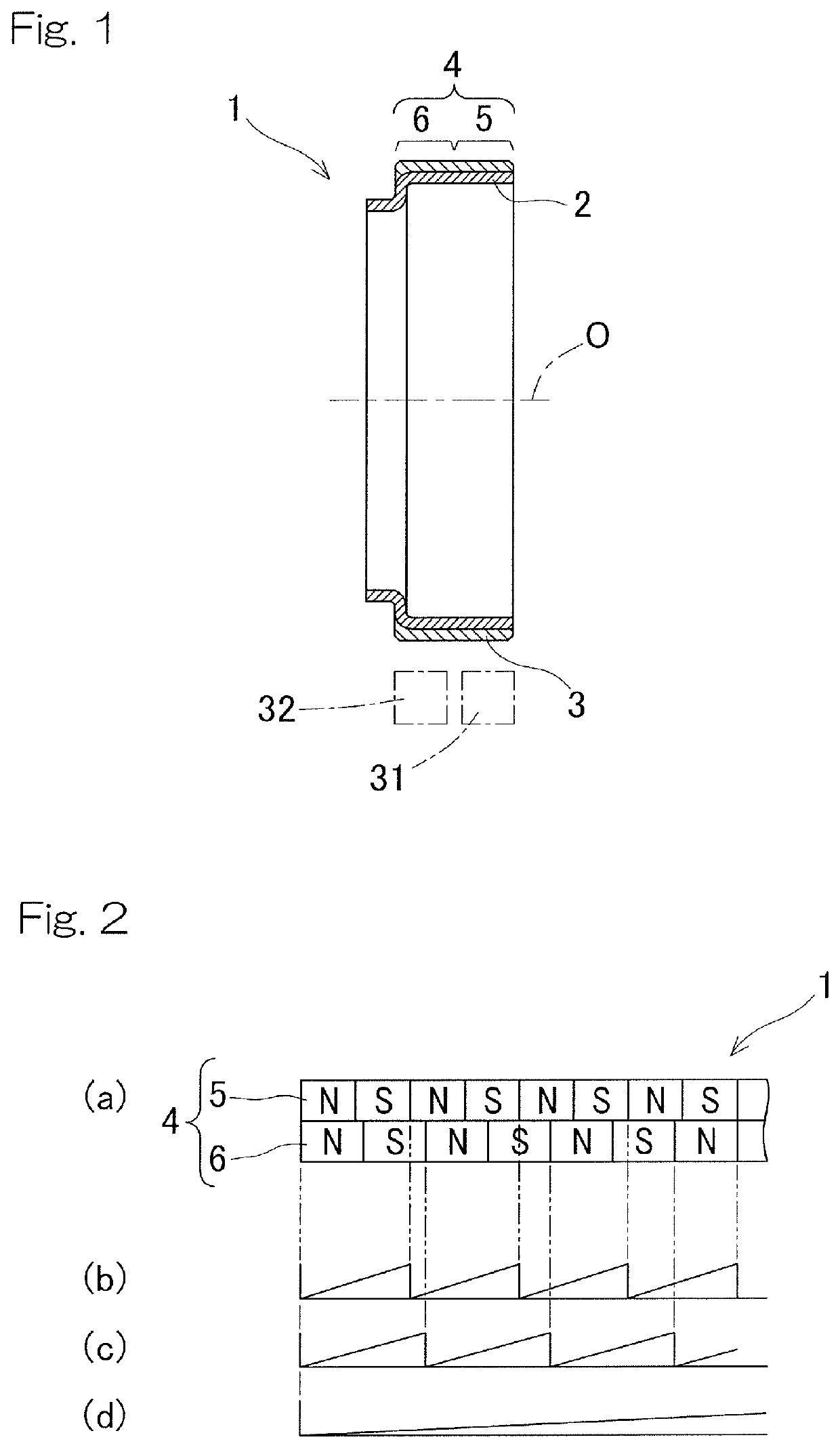
[0030]An embodiment of the present invention will be described with reference to the drawings. FIG. 1 is a longitudinal-sectional view of a magnetic encoder. In FIG. 2, chart (a) shows magnetization patterns of magnetic tracks developed in the circumferential direction, charts (b) and (c) show detection signals corresponding to respective magnetic pole pairs in the magnetization patterns, and chart (d) shows a phase difference between the detection signals.

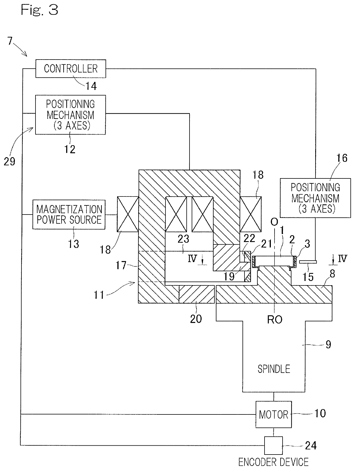
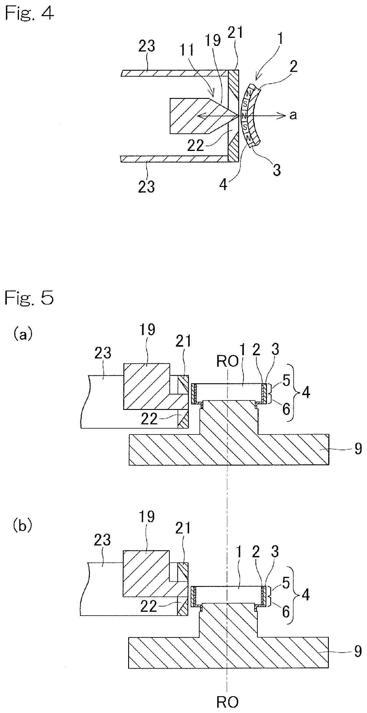
[0031]The magnetic encoder 1 is produced as follows. A rubber material, in which a magnetic powder is kneaded, is put in a mold together with a core member 2 which is a metal ring, and is bonded through vulcanization to the outer peripheral surface of the core member 2 to form an annular magnetic member 3. Alternatively, a core member 2 and a mixture of a plastic material and a magnetic powder are integrally molded to form an annular magnetic member 3 on the outer peripheral surface of the core member 2. Then, a plurality of rows ...


PUM


Abstract

Provided is a magnetic encoder that can be produced by a simple modification of an existing production method and that can detect an absolute angle with high efficiency, and a method and an apparatus for producing the magnetic encoder. In a magnetic encoder, a plurality of rows of magnetic tracks, each having N poles and S poles arranged alternately, are disposed adjacent to each other. The rows of magnetic tracks include a main track used for calculating an angle and a sub track used for calculating a phase difference from the main track. The number of magnetic poles of the main track is larger than that of the sub track. The main track is magnetized after the sub track. Thus, accuracy of pitch of the magnetic poles is higher in the main track than in the sub track.

Description

CROSS REFERENCE TO THE RELATED APPLICATION[0001]This application is a continuation application, under 35 U.S.C. § 111(a), of international application No. PCT / JP2018 / 002827, filed Jan. 30, 2018, which is based on and claims Convention priority to Japanese patent application No. 2017-017303, filed Feb. 2, 2017, the entire disclosure of which is herein incorporated by reference as a part of this application.BACKGROUND OF THE INVENTIONField of the Invention[0002]The present invention relates to a magnetic encoder used for detecting a rotation speed or a rotation position, and a method and an apparatus for producing the magnetic encoder. In particular, the present invention relates to a technology applicable to: a magnetic encoder having a plurality of rows of magnetic encoder tracks or magnetic tracks that are used for detecting an absolute angle; and a method and an apparatus for producing the magnetic encoder.Description of Related Art[0003]A magnetic encoder device disclosed in Pate...

Claims


Application Information

Patent Timeline
IPC IPC(8): G01D5/245G01D5/244G01D5/14
CPCG01D5/2452G01D5/24438G01D5/14G01D5/245G01D5/2451H01F13/003
Inventor KOIKE, TAKASHIFUKUSHIMA, YASUYUKIYAMAGUCHI, YUYA
Owner NTN CORP
Why Eureka
Try Eureka