Fire Extinguishing Equipment

a technology for fire extinguishing equipment and equipment, applied in fire rescue and other directions, can solve problems such as damage similar, damage, and damage to sprinkler heads, and achieve the effect of slow reduction lowering of pressure in primary piping

Inactive Publication Date: 2019-11-21
SENJU SPRINKLER
View PDF4 Cites 2 Cited by
  • Summary
  • Abstract
  • Description
  • Claims
  • Application Information

AI Technical Summary

Benefits of technology

[0009]With the present invention, the cross-sectional area of the minimum flow passage diameter portion of the relief valve is smaller than the cross-sectional area of the nozzle outlet of the sprinkler head. Therefore, when a fire occurs, the amount of water supplied from the secondary piping to the primary piping through the relief valve in a non-fire system is less than the flow rate of water discharged from the sprinkler head in the fire system. Thus, the amount of water supplied from the relief valve in the non-fire system, which may cause a slow reduction in the pressure in the primary piping, can be suppressed. Consequently, the pump start switch is actuated with the pressure in the primary piping lowered without delay. Then, sufficient water is fed from the pump to the sprinkler head for the fire protection area in which a fire is caused. The “minimum flow passage diameter portion” discussed above indicates a portion at which the cross-sectional area of a portion that enables passage of a fluid on a virtual plane that perpendicularly intersects the center axis of the relief valve is minimum.

Problems solved by technology

In summer, in particular, the water in the secondary piping is expanded and pressurized, which may break the sprinkler head.
In winter, meanwhile, the water in the secondary piping is compressed and pressurized when the water in the piping is frozen and expanded in volume, which may cause a damage similar to that described above.
Consequently, although the sprinkler head Sa is actuated in the fire protection area in which a fire is caused, sufficient water may not be fed with actuation of the pump start switch 5 delayed, which may disturb initial fire fighting.

Method used


Image

  • Fire Extinguishing Equipment
  • Fire Extinguishing Equipment
  • Fire Extinguishing Equipment

Examples


first embodiment

Modification of First Embodiment

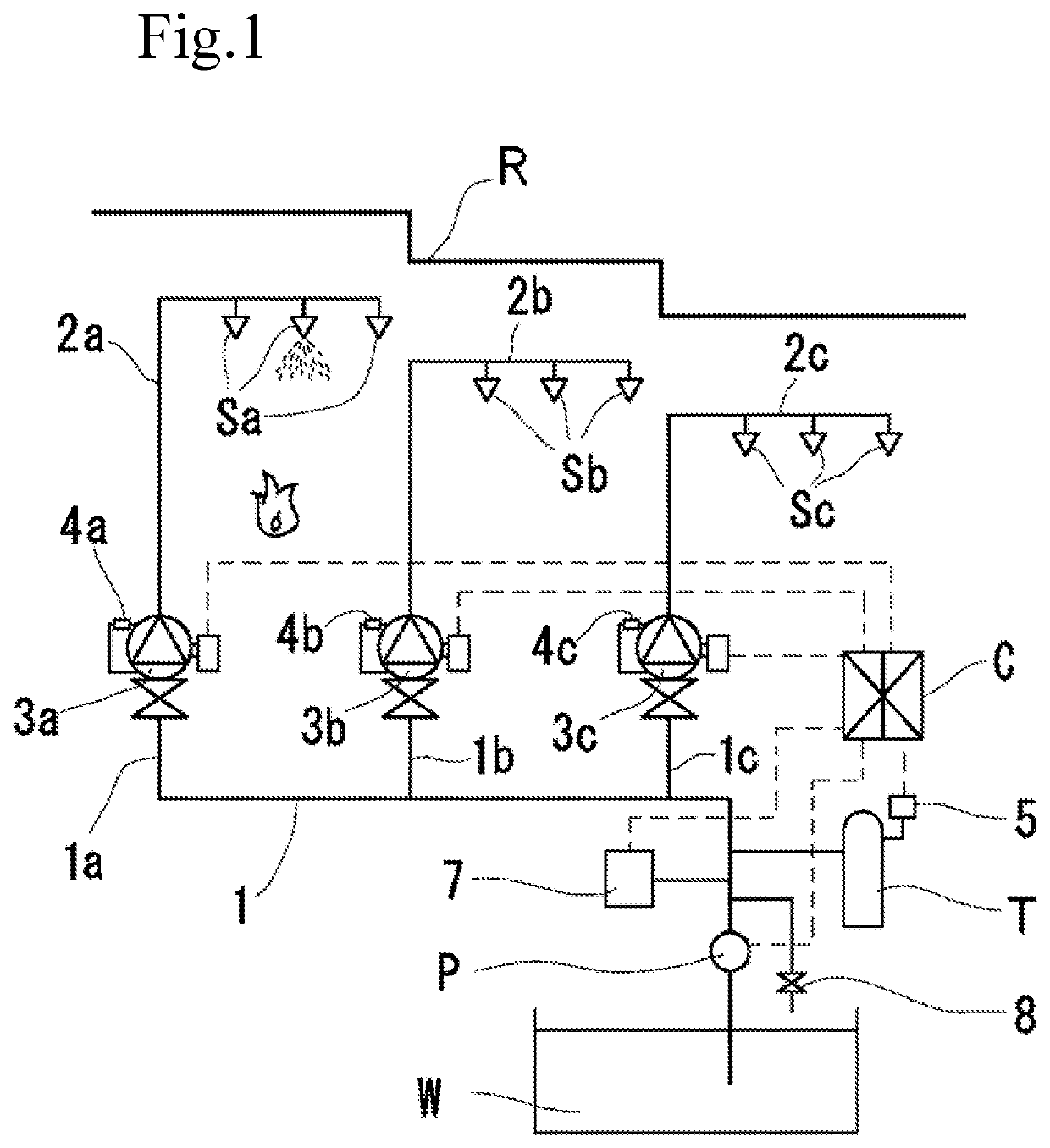
[0052]Next, a modification of the first embodiment will be described. In this modification, the pressure difference (first pressure difference) at the time when the relief valve 4 is opened is larger than the pressure difference (third pressure difference) between the pressure of water in the secondary piping 2 at normal times and the set pressure at which the pump start switch 5 is actuated. Components that are identical to those according to the first embodiment are given identical reference numerals to omit overlapping description.

[0053]In the FIRE EXTINGUISHING EQUIPMENT, the pressure in the secondary piping 2 is set to be higher than the pressure in the primary piping 1 at normal times (in the absence of a fire), and the pump P can be started before the relief valve 4 is opened at the time of a fire. For example, when the pressure in the secondary piping 2 is 1 MPa, the pressure in the primary piping 1 is lower at 0.9 MPa. The actuation pressure ...


PUM


Abstract

A FIRE EXTINGUISHING EQUIPMENT includes a pump that feeds water to piping, a water flow detection device connected to the pump, a sprinkler head connected to secondary piping of the water flow detection device, and a pump start switch installed in primary piping between the pump and the water flow detection device. The primary piping is divided in correspondence with plural fire protection areas. The water flow detection device is installed in each branch of the primary piping. A relief valve provided in bypass piping that connects between the primary piping and the secondary piping not via the water flow detection device is opened when the difference between the primary-side and secondary-side pressures is equal to or more than a predetermined value. The cross-sectional area of a minimum flow passage diameter portion of the relief valve is smaller than the cross-sectional area of a nozzle outlet of the sprinkler head.

Description

BACKGROUND OF THE INVENTION1. Field of the Invention[0001]The present invention relates to a FIRE EXTINGUISHING EQUIPMENT such as a sprinkler equipment and a foam FIRE EXTINGUISHING EQUIPMENT.2. Description of the Related Art[0002]A FIRE EXTINGUISHING EQUIPMENT such as a sprinkler equipment and a foam FIRE EXTINGUISHING EQUIPMENT includes a water flow detection device installed on piping that extends from a water source to a sprinkler head or a foam head. The water flow detection device has a check valve structure, and allows passage of water in one direction from the water source to the sprinkler head or the foam head only. Water charged inside secondary piping, in which the sprinkler head is installed, is expanded and contracted because of seasonal temperature differences. In summer, in particular, the water in the secondary piping is expanded and pressurized, which may break the sprinkler head. In winter, meanwhile, the water in the secondary piping is compressed and pressurized ...

Claims


Application Information

Patent Timeline
Patent Type & Authority Applications(United States)
IPC IPC(8): A62C35/68A62C35/64
CPCA62C35/64A62C35/68A62C31/005A62C31/28A62C37/00A62C5/02A62C35/60A62C5/002
Inventor KON, YUKIHIROCHIBA, SHOU
Owner SENJU SPRINKLER
Why Eureka
Try Eureka