Heat-wing

a technology of heat radiator and heat-wing, which is applied in the direction of heat-exhanger fins, basic electric elements, lighting and heating apparatus, etc., can solve the problem that the heat pipe tends to reach the heat transfer limit, and achieve the effect of large working medium flow-back passage width, large condenser heat dissipation area, and high heat transfer limi

Active Publication Date: 2019-11-21
ZHANG YUE
View PDF12 Cites 0 Cited by
  • Summary
  • Abstract
  • Description
  • Claims
  • Application Information

AI Technical Summary

Benefits of technology

[0006]It is therefore an objective of the present invention to provide a phase-change heat radiator with a large vapor passage area, large working medium flow-back passage width, short evaporator center-to-edge distance, large condenser heat dissipation area and high heat transfer limit.

Problems solved by technology

Moreover, limited by the narrow ducts for vapor transport and a minimal flow-back passage width of the liquid working medium, the heat pipe tends to reach its heat transfer limit before operating at the optimal performance level.

Method used


Image

  • Heat-wing
  • Heat-wing
  • Heat-wing

Examples


first embodiment

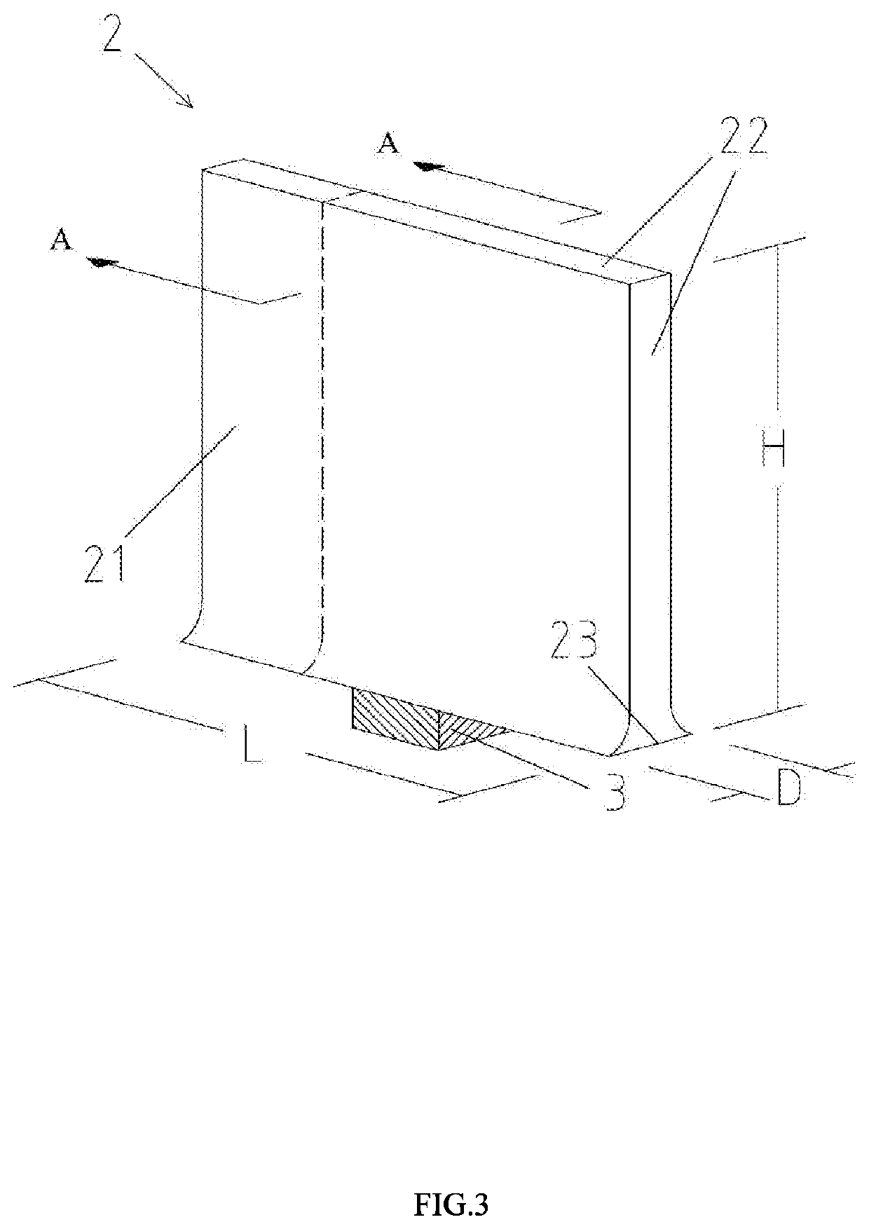
[0043]the present invention is shown in FIGS. 3 and 4. As illustrated, the heat-wing of the present invention includes a chamber 2 which is essentially a hollow plate-shaped structure including the first plate 20, the second plate 21 and a second portion 22 of the frame and a first portion 23 of the frame connecting the two plates (20 and 21). The heat-wing further includes a capillary structure layer 12 which is closely attached to an inner surface of the chamber 2, and a phase transition working medium 13 hermetically sealed in the chamber 2. The first outside surface portion of the frame 23 comes in contact with a heat source 3, and thus functions as an evaporation area, while the rest portion of the chamber 2 acts as a condensation area. Alternatively, it is also possible to use a portion of a periphery of one of the first plate 20 and the second plate 21 to serve as the evaporation area.

[0044]Each of a length and a height of the heat-wing is much greater than a thickness of the...

seventh embodiment

[0058]FIG. 10 shows the present invention. As illustrated, in this embodiment, a plurality of the heat-wings of FIG. 3 are arranged in an array and disposed on a heat source, totally covering the top surface of the heat source. Such array arrangement expands the two-dimensional phase-change heat transfer into a three-dimensional space and hence can achieve a higher heat flux density.

[0059]FIGS. 11 and 12 show an eighth embodiment of the present invention. As illustrated, in this embodiment, a plurality of the J-shaped heat-wings of FIG. 7 are arranged in an array and disposed on a heat source, totally covering the top surface of the heat source. Differing from the seventh embodiment, each heat-wing of the array of this embodiment is bent to project laterally from the heat source and is thus particularly suitable for applications where there exists a height limitation.

ninth embodiment

[0060]FIG. 13 shows a three-dimensional view of a heat-wing array in accordance with the present invention.


PUM


Abstract

A heat-wing includes: a sealed hollow chamber including two plates and a frame connecting the two plates; a capillary structure layer closely attached to an inner surface of the chamber; and a phase transition working medium sealed in the chamber. A portion of the frame or a portion of a periphery of one of the two plates serves as an evaporation area of the heat-wing, and the rest portion of the chamber serves as a condensation area of the heat-wing. The heat-wing has an increased vapor passage area, liquid working medium flow-back passage width and condenser heat transfer area and a reduced evaporator center-to-edge distance, and is hence capable of achieving a great improvement in heat transfer limit and heat flux density.

Description

TECHNICAL FIELD[0001]The present invention relates generally to phase-change heat radiators, and particularly to a heat-wing and use thereof.BACKGROUND[0002]Compared to high thermal conductivity solid metal blocks, phase-change heat radiators have higher equivalent thermal conductivities and better heat dissipation performance. They are widely used because of a variety of advantages, such as a high thermal conductivity and good temperature uniformity. These advantages are realized by liquid working media sealed in the heat radiators, on the phase transition of which the heat radiators rely for heat transfer. Currently, heat pipes and vapor chambers are two types of commonly used phase-change heat radiators.[0003]Referring to FIG. 1, a typical heat pipe is composed of a hollow cylindrical chamber 11, a capillary structure 12 and a phase transition working medium 13 hermetically sealed in the chamber. Fabrication of the heat pipe generally includes: vacuuming the chamber and partially...

Claims


Application Information

Patent Timeline
Patent Type & Authority Applications(United States)
IPC IPC(8): F28D15/02F28D15/04
CPCF28D15/04F28D15/0233F28D15/0275F28F2215/06H01L23/427H01L23/3672
Inventor ZHANG, YUE
Owner ZHANG YUE
Why Eureka
Try Eureka