Check patentability & draft patents in minutes with Patsnap Eureka AI!

Cable wrap mechanism

a technology of cable and wire, which is applied in the direction of insulated conductors, cables, conductors, etc., can solve the problems of large number of electrical wires required for the electric propulsion thruster, and achieve the effect of reducing the resistance force against bending in the electrical wire band and reducing the electromagnetic induction noise generated by the electrical wire band

Active Publication Date: 2019-11-28
MITSUBISHI ELECTRIC CORP
View PDF25 Cites 1 Cited by
  • Summary
  • Abstract
  • Description
  • Claims
  • Application Information

AI Technical Summary

Benefits of technology

The invention reduces resistance in the electrical wire band and reduces noise caused by electromagnetic induction, making it easier to wind the wire into a spiral spring shape. This results in a larger number of electrical wires being able to pass through a movable mechanism that adjusts the arrangement of an electrical propulsion thruster.

Problems solved by technology

Since a large current is required to flow in an electric propulsion thruster mounted on an artificial satellite, the number of electrical wires required for the electric propulsion thruster is large.
Further, since an electromagnetic induction noise is generated from an electrical wire when the large current flows through the electrical wire, implementation to minimize the electromagnetic induction noise generated from the electrical wire is required.

Method used


Image

  • Cable wrap mechanism
  • Cable wrap mechanism
  • Cable wrap mechanism

Examples


embodiment 1

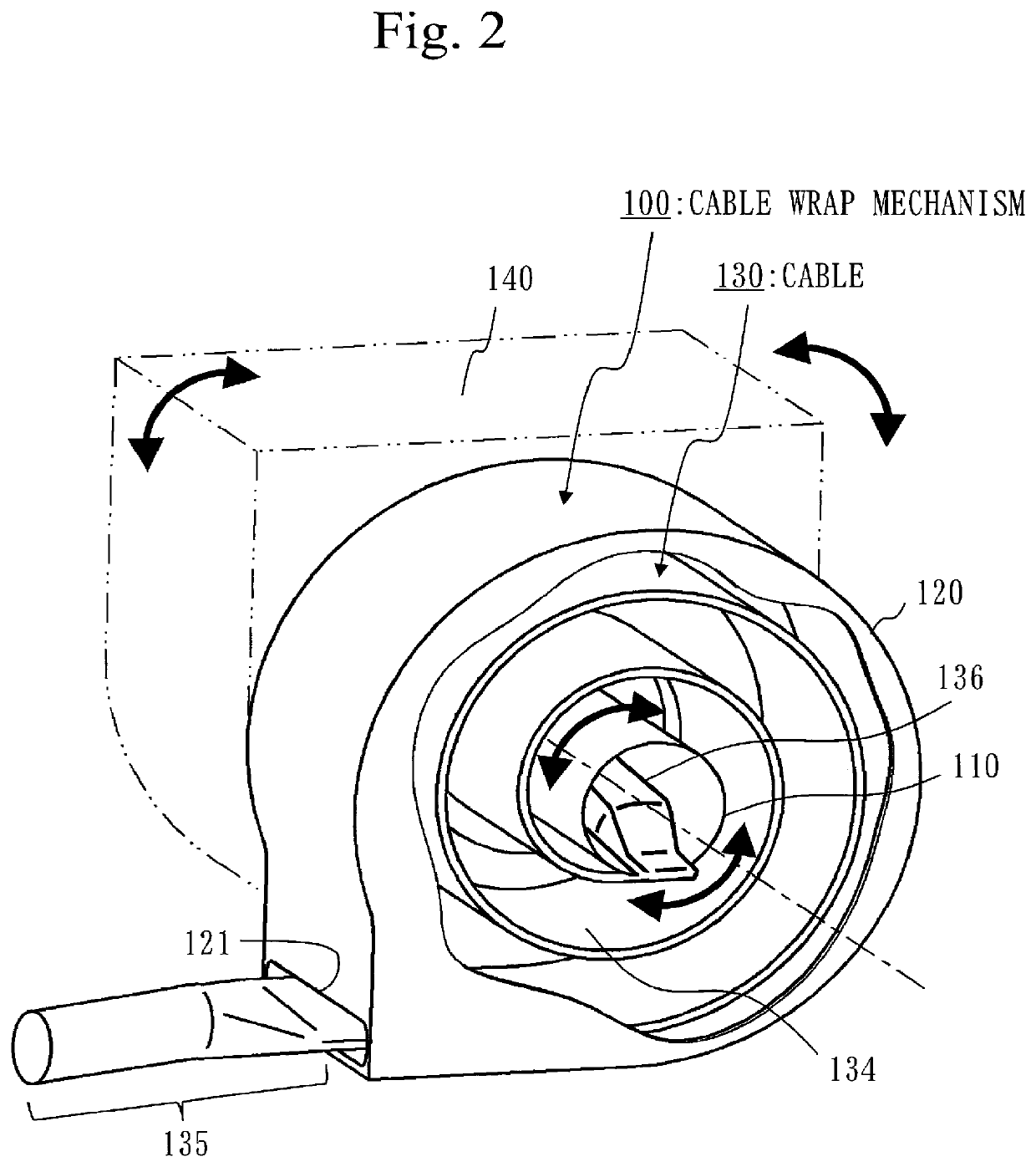
[0019]A cable wrap mechanism in which a part of a cable is wound and accommodated in a spiral spring shape will be described with reference to FIGS. 1 and 2.

Description of Structures

[0020]Structures of a cable wrap mechanism 100 and a cable 130 will be described with reference to FIG. 1.

[0021](A) of FIG. 1 is a perspective view illustrating the interior of the cable wrap mechanism 100. (B) of FIG. 1 is an enlarged cross-sectional view of the cable 130 in a portion indicated by broken lines illustrated in (A) of FIG. 1.

[0022]In the embodiment 1, the cable wrap mechanism 100 and the cable 130 are components used for an artificial satellite.

[0023]Specifically, the cable wrap mechanism 100 is connected to a movable portion 140 of a thruster pointing mechanism. The thruster pointing mechanism adjusts an arrangement of a thruster. The movable portion 140 is a bracket that supports the thruster pointing mechanism and can be rotated. A dashed line with one dot passing through a shaft 110 re...

embodiment 2

[0062]With regard to an embodiment in which the electromagnetic induction noise is further reduced, differences from the embodiment 1 will mainly be described with reference to FIG. 3.

Description of Structure

[0063]As illustrated in FIG. 3, a first electrical wire 131 is in close contact with an adjacent second electrical wire 132 in the electrical wire band 134.

[0064]Further, a surface and a back surface of the electrical wire band 134 are covered with an adhesive film 137 in a state where the first electrical wire 131 is in close contact with the adjacent second electrical wire 132. In FIG. 3, the entire electrical wire band 134 is covered with the adhesive film 137.

[0065]The adhesive film 137 is a film having adhesiveness. For example, the adhesive film 137 is a polyimide tape in which a pressure sensitive adhesive or an adhesive agent is adhered to a polyimide film.

[0066]The adhesive film 137 is stuck to the electrical wire band 134 in a state where the first electrical wire 131 ...


PUM


Abstract

A cable (130) includes an electrical wire band (134). A parallel electrical wire (133) is formed by arranging a pair of a first electrical wire (131) and a second electrical wire (132) without being twisted together. The electrical wire band is formed by arranging a plurality of parallel electrical wires in a lateral row. In addition, between two adjacent parallel electrical wires, a second electrical wire of one parallel electrical wire is arranged adjacently to a first electrical wire of the other parallel electrical wire. Further, the electrical wire band is wound and accommodated in a spiral spring shape in a cable wrap mechanism (100).

Description

TECHNICAL FIELD[0001]The present invention relates to a mechanism that accommodates a part of a cable used for electrical equipment of an artificial satellite.BACKGROUND ART[0002]Since a large current is required to flow in an electric propulsion thruster mounted on an artificial satellite, the number of electrical wires required for the electric propulsion thruster is large.[0003]In addition, in order to adjust an arrangement of the electric propulsion thruster, it is necessary to pass a large number of electrical wires through a movable portion of a mechanism that adjusts the arrangement of the electric propulsion thruster.[0004]Further, when resistance force against bending in an electrical wire is large, it is necessary to strengthen a power source such as a motor used for an adjustment mechanism. Therefore, implementation to minimize the resistance force is required.[0005]Further, since an electromagnetic induction noise is generated from an electrical wire when the large curre...

Claims


Application Information

Patent Timeline
Patent Type & Authority Applications(United States)
IPC IPC(8): B64G1/42H02G11/02
CPCH01B7/0892H02G11/02B64G1/428B64G1/22H05K9/00
Inventor KAWAMURA, SHUNICHI
Owner MITSUBISHI ELECTRIC CORP
Features
  • R&D
  • Intellectual Property
  • Life Sciences
  • Materials
  • Tech Scout
  • Unparalleled Data Quality
  • Higher Quality Content
  • 60% Fewer Hallucinations
Learn More