Manufacture of spun-bonded nonwoven from continuous filaments

Active Publication Date: 2019-11-28
REIFENHAUSER GMBH & CO
View PDF0 Cites 4 Cited by
  • Summary
  • Abstract
  • Description
  • Claims
  • Application Information

AI Technical Summary

Benefits of technology

[0039]When filaments or spunbonded nonwovens are made according to the invention from polyolefins, particularly polypropylene, it is possible to work at yarn speeds or filament speeds of over 2000 m/min, particularly over 2200 m/min or over 2500 m/min. If filaments or spunbonded nonwovens are made from polyesters, particularly polyethylene terephthalate (PET), in the context of the invention, yarn speeds of over 4000 m/min, particularly including over 5000 m/min, can be achieved. The cited yarn speeds can be achieved, above all, without any loss of quality in the course of the measures according to the invention. It lies within the scope of the invention for the apparatus according to the invention to be configured or set up with the understanding that it is possible to work at the above-described yarn speeds. The inventive design of the manifolds has proven to be particularly useful at these high yarn speeds. According to one embodiment of the method according to the invention, throughputs of greater than 150 kg/h/m or greater than 200 kg/h/m are used.
[0040]The invention is based on the discovery that, with the apparatus according to the invention and with the method according to the invention, spunbonded nonwovens of outstanding quality can be achieve

Problems solved by technology

However, the majority of these known apparatuses and methods have the disadvantage that the spunbonded nonwovens made with them are not always sufficiently homogeneous or uniform over their surface extension.
Frequently, the spunbonded nonwovens made in this way have objectionable inhomoge

Method used


Image

  • Manufacture of spun-bonded nonwoven from continuous filaments
  • Manufacture of spun-bonded nonwoven from continuous filaments
  • Manufacture of spun-bonded nonwoven from continuous filaments

Examples


Embodiment Construction

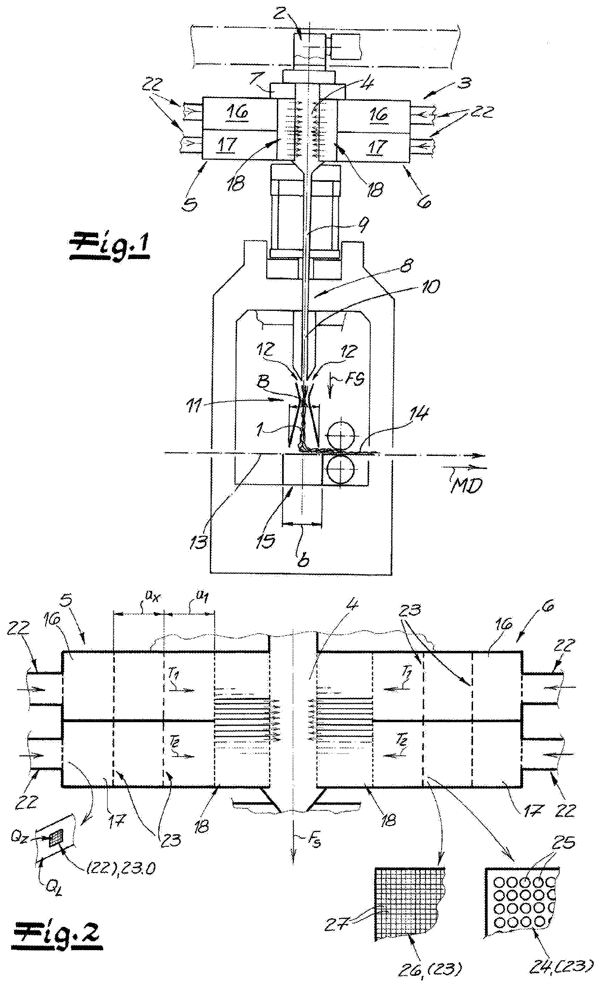
[0049]As seen in FIG. 1, an apparatus according to the invention for making spunbonded nonwovens from continuous filaments 1, particularly from continuous thermoplastic filaments 1 has a spinneret 2 for spinning the continuous filaments 1. These spun continuous filaments 1 are emitted into a cooler 3 with a cooling chamber 4 and with two manifolds 5 and 6 that are on opposite sides of the cooling chamber 4. The cooling chamber 4 and the manifolds 5 and 6 extend transverse to the machine direction MD and thus in the CD direction of the apparatus. Cooling air is fed from the oppositely situated manifolds 5 and 6 into the cooling chamber 4.

[0050]Preferably and in this embodiment, a monomer extractor 7 is provided between the spinneret 2 and the cooler 3. With this monomer extractor 7, objectionable gases generated by the spinning process can be removed from the apparatus. These gases can be monomers, oligomers, or decomposition products and similar substances, for example.

[0051]In the ...


PUM

PropertyMeasurementUnit
Lengthaaaaaaaaaa
Fractionaaaaaaaaaa
Fractionaaaaaaaaaa

Abstract

An apparatus for making spunbonded nonwovens has a spinneret for emitting continuous thermoplastic filaments in a filament-travel direction, a cooling chamber downstream in the direction from the spinneret for cooling the spun filaments with cooling air, two manifolds on opposite sides of the cooling chamber opening transversely of the direction into the cooling chamber, and a respective conduit having a conduit cross-sectional area and connected to each manifold for feeding cooling air thereto. The conduit cross-sectional area increases toward the manifold to a manifold cross-sectional area, and manifold cross-sectional area is at least twice as large as the conduit cross-sectional area. At least one flow straightener is provided upstream from the cooling chamber in each manifold for orienting air flow in an air-flow direction, and at least one perforated planar homogenizing element is provided in each manifold for homogenizing the cooling air flow.

Description

FIELD OF THE INVENTION[0001]The present invention relates to the manufacture of spunbonded nonwovens. More particularly this invention concerns a method and apparatus for making such nonwovens from continuous filaments.BACKGROUND OF THE INVENTION[0002]A known apparatus for making spunbonded nonwovens from continuous filaments, particularly from continuous filaments made of thermoplastic, has a spinneret for spinning the continuous filaments, a cooling chamber for cooling the spun filaments with cooling air, manifolds flanking the cooling chamber so that cooling air can be introduced into the cooling chamber from the oppositely situated manifolds, and at least one conduit for feeding cooling air connected to each manifold.[0003]In the context of the invention, “spunbonded nonwoven” refers particularly to a spunbond fabric that is made by the spunbond process. Continuous filaments differ from staple fibers on account of their quasi endless length, whereas staple fibers have substantia...

Claims


Application Information

Patent Timeline
IPC IPC(8): D04H1/736D04H3/077D04H1/76
CPCD04H3/033D04H3/11D04H3/16D04H3/005D01D5/092D01D13/02D01D5/088D01D5/0985D01F8/04D04H1/736D04H1/76D04H3/077
Inventor NITSCHKE, MICHAELNEUENHOFER, MARTINGEUS, HANS-GEORGFREY, DETLEF
Owner REIFENHAUSER GMBH & CO
Why Eureka
Try Eureka