Engine spray flow field near-field region optical diagnosis system

An optical diagnosis, engine technology, applied in fluid dynamics test, fluid velocity measurement, testing of machine/structural components, etc., to achieve the effect of improving the signal-to-noise ratio

Inactive Publication Date: 2014-04-09
XI AN JIAOTONG UNIV
View PDF4 Cites 7 Cited by
  • Summary
  • Abstract
  • Description
  • Claims
  • Application Information

AI Technical Summary

Problems solved by technology

Therefore, conventional flow field measurement methods such as shadow method, digital holography method, LIF method and other optical imaging and diagnostic technologies exist in the observation of the near-field region of the ultra-high-speed spray flow field of rocket engines and the combustion process of internal combustion engines under high temperature and high pressure. Problems: (1) In the near-field region, most of the photons used for imaging are scattered by dense liquid droplets, and ordinary flow field optical observation technology cannot be applied to the diagnosis in this region; (2) Measurement of particle motion in ultra-high-speed flow field For speed and acceleration, the frame frequency of the imaging system needs to reach the order of MHz or tens of MHz. Therefore, increasing the frame frequency of the imaging system and ensuring that the frame frequency can be adjusted is to measure the diffusion velocity between the liquid phase and the gas phase interface in the ultra-high-speed spray field. The key to acceleration and acceleration, obtaining these data is the premise of analyzing the rupture process of the liquid core under the action of external force

Method used


Image

  • Engine spray flow field near-field region optical diagnosis system
  • Engine spray flow field near-field region optical diagnosis system
  • Engine spray flow field near-field region optical diagnosis system

Examples


Embodiment Construction

[0028] Below in conjunction with accompanying drawing, the present invention is described in further detail:

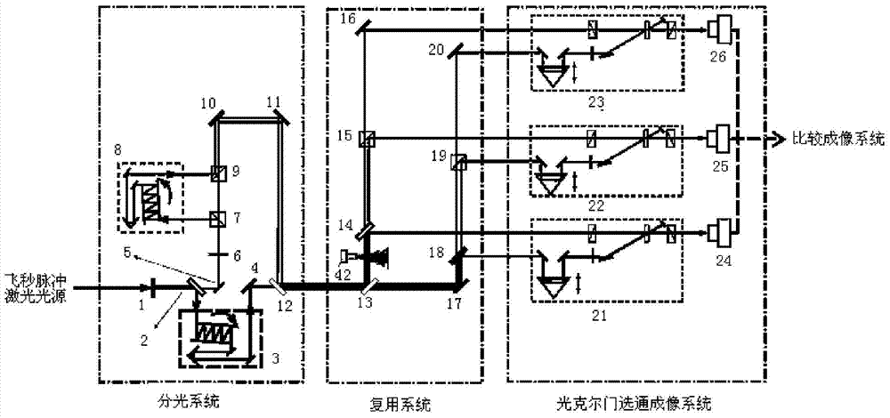
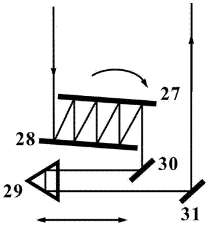
[0029] see Figure 1-2 , the ultra-high-speed flow field velocity and acceleration measurement system of the present invention includes a spectroscopic system, a multiplexing system, an optical Kerr gate strobe imaging system, and a comparative imaging system placed sequentially along the incident direction of the femtosecond pulsed laser; the spectroscopic system, multiplexing system of the present invention All optical components of the system, the optical Kerr gate gated imaging system and the comparative imaging system are mounted on an optical anti-vibration platform, and the planes of each component are perpendicular to the plane of the anti-vibration table.

[0030] The spectroscopic system is used to convert the femtosecond pulsed laser into a pulse train with nanosecond intervals consisting of frequency doubled light, horizontally polarized fundamental freque...


PUM


Abstract

An engine spray flow field near-field region optical diagnosis system comprises a light splitting system, a multiplexing system, an optical Kerr gate strobing imaging system, and a comparison imaging system, which are disposed along the incident direction of femtosecond pulse laser. The light splitting system split the incident femtosecond pulse laser into three beams of light pulses which are different in wavelength and polarization characteristic and adjustable in time interval. The three beams of light pulses respectively record information of a spray flow field near-field region at different time points through the multiplexing system and then go through the optical Kerr gate strobing imaging system for imaging respectively. The optical Kerr gate strobing trajectory light imaging system can be used to effectively remove the influence of diffusion light and increase the imaging signal-to-noise ratio. The particle speed and acceleration information can be calculated through a single particle track in three flow field graphs recorded by the comparison imaging system.

Description

technical field [0001] The invention belongs to the field of ultra-high-speed flow field high-resolution imaging and measurement, and in particular relates to an optical diagnosis system for the near-field region of the engine spray flow field. Background technique [0002] In internal combustion engines such as liquid rocket engines, gasoline engines, and diesel engines, the injector atomizes the fuel and mixes it with the surrounding oxidant. The atomization fineness and mixing uniformity directly affect the combustion performance of the internal combustion engine. The atomization process and injection characteristics of fuel are affected by external factors such as injection pressure, fuel viscosity, cylinder pressure, temperature, and airflow movement, as well as internal structural factors such as the structure of the injector and the shape of the combustion chamber. By studying the droplet distribution, velocity distribution, flow field strength and mixing ratio of fue...

Claims


Application Information

Patent Timeline
Patent Type & Authority Applications(China)
IPC IPC(8): G01M10/00G01P5/18G01P15/00
Inventor 闫理贺司金海谭文疆陈涛陈烽侯洵
Owner XI AN JIAOTONG UNIV
Why Eureka
Try Eureka