
Method for applying driving voltage for liquid lens, camera module, and optical instrument including the module

a driving voltage and liquid lens technology, applied in the direction of instruments, camera body details, focusing aids, etc., can solve the problems of increasing the overall thickness of the optical device, the high power consumption of the lens moving apparatus, etc., to reduce the amount of power consumed by the optical device, and increase the auto-focusing resolution

Active Publication Date: 2019-11-28
LG INNOTEK CO LTD
View PDF0 Cites 2 Cited by
  • Summary
  • Abstract
  • Description
  • Claims
  • Application Information

AI Technical Summary

Benefits of technology

The present invention relates to a device that can increase the autofocus resolution of a camera by using a constant output voltage range of a voltage driver. This can improve the quality of photos captured by the camera without requiring an increase in the output voltage range of the voltage driver. Additionally, this can lead to a reduction in power consumption by the camera.

Problems solved by technology

However, the lens moving apparatus has high power consumption, and an additional cover glass needs to be provided separately from the camera module in order to protect the lens moving apparatus, thus leading to an increase in the overall thickness of an optical device.

Method used


Image

  • Method for applying driving voltage for liquid lens, camera module, and optical instrument including the module
  • Method for applying driving voltage for liquid lens, camera module, and optical instrument including the module
  • Method for applying driving voltage for liquid lens, camera module, and optical instrument including the module

Examples


Embodiment Construction

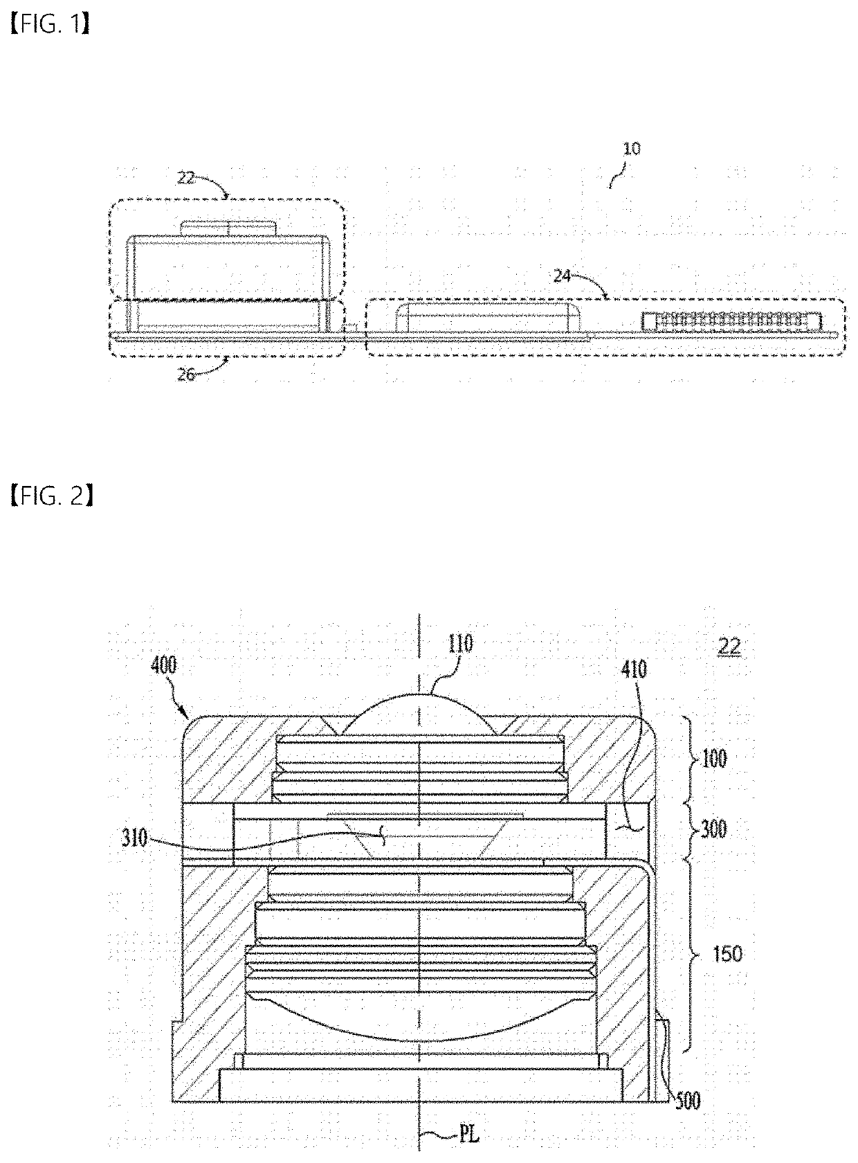
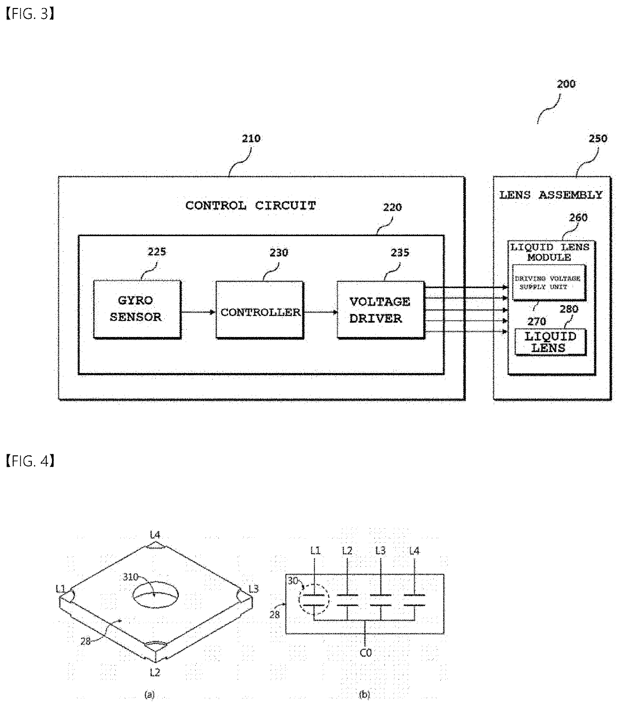
[0047]Reference will now be made in detail to the preferred embodiments, examples of which are illustrated in the accompanying drawings. While the disclosure is subject to various modifications and alternative forms, specific embodiments thereof are shown by way of example in the drawings. However, the disclosure should not be construed as being limited to the embodiments set forth herein, but on the contrary, the disclosure covers all modifications, equivalents, and alternatives falling within the spirit and scope of the embodiments.

[0048]It may be understood that, although the terms “first”, “second”, etc. may be used herein to describe various elements, these elements are not to be limited by these terms. These terms are generally only used to distinguish one element from another. In addition, terms particularly defined in consideration of the construction and operation of the embodiments are used only to describe the embodiments, but do not define the scope of the embodiments.

[0...


PUM


Abstract

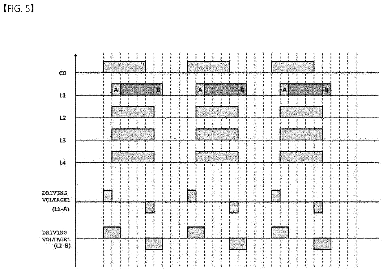
A camera module according to an embodiment of the present invention includes a first plate including a cavity formed therein to accommodate a conductive liquid and a non-conductive liquid; an electrode unit disposed on the first plate, the electrode unit being electrically connected to an external power source to change an interface between the conductive liquid and the non-conductive liquid; an insulation unit disposed on the electrode unit and a control unit controlling a voltage applied to the electrode unit, wherein the electrode unit includes a first electrode and a second electrode electromagnetically interacting with each other to change the interface, wherein the first electrode includes a plurality of electrode sectors arranged sequentially in a clockwise direction with respect to an optical axis, and wherein the control unit performs control so as to apply voltages to driving electrodes by rotation in a clockwise direction or in a counterclockwise direction.

Description

CROSS REFERENCE TO RELATED APPLICATIONS[0001]This application is the National Phase of PCT International Application No. PCT / KR2018 / 000603, filed on Jan. 12, 2018, which claims priority under 35 U.S.C. 119(a) to Patent Application No. 10-2017-0006224, filed in Republic of Korea on Jan. 13, 2017 and Patent Application No. 10-2017-0046984, filed in Republic of Korea on Apr. 11, 2017, all of which are hereby expressly incorporated by reference into the present application.TECHNICAL FIELD[0002]The present disclosure relates to a method of applying a driving voltage to a liquid lens, a camera module, and an optical device including the module. More particularly, the present disclosure relates to a method of applying a driving voltage to a liquid lens enabling adjustment of a focal length using electrical energy, a camera module, and an optical device including the module.BACKGROUND ART[0003]People who use portable devices demand optical devices that have high resolution, are small, and h...

Claims


Application Information

Patent Timeline
Patent Type & Authority Applications(United States)
IPC IPC(8): G03B13/36G02B26/00G02B3/14
CPCG02B3/14G03B13/32G03B17/12G02B27/646H04N23/00H04N23/60G02B26/004G03B13/36
Inventor MOON, YOUNG SEOPKIM, HOON
Owner LG INNOTEK CO LTD
Learn More