Error checking for primary signal transmitted between first and second clock domains

a clock domain and error checking technology, applied in the field of integrated circuits, can solve problems such as the complexity of the transmission of clock signals across the clock domain boundary

Active Publication Date: 2019-11-28
ARM LTD
View PDF0 Cites 7 Cited by
  • Summary
  • Abstract
  • Description
  • Claims
  • Application Information

AI Technical Summary

Problems solved by technology

This can make transmission of clock signals across the clock domain boundary more complex.

Method used


Image

  • Error checking for primary signal transmitted between first and second clock domains
  • Error checking for primary signal transmitted between first and second clock domains
  • Error checking for primary signal transmitted between first and second clock domains

Examples


Embodiment Construction

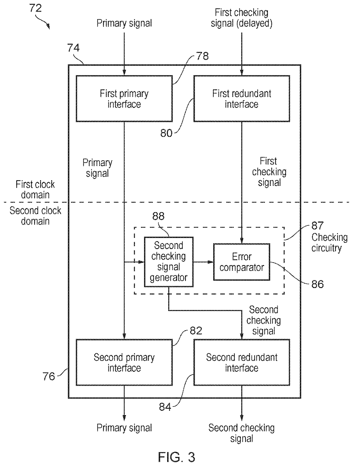
[0036]The functional safety of an integrated circuit may be improved by operating components in lockstep, in which the components operate in a redundant manner with a fixed time delay between signals sent between the primary components and corresponding signals sent between the redundant components, and a primary signal and a redundant checking signal are duplicated and compared to one another to check for any errors. The fixed temporal delay between the primary components and redundant components may be zero, or non-zero. A non-zero delay can improve robustness against error as it is less likely that an event at a particular time that causes an error in the primary signal also causes the same error in the checking signal, or vice versa. However, in some cases a fixed time delay of zero can still provide sufficient error detection percentage to comply with some classifications of functional safety required for some applications.

[0037]However, such safety features can be difficult to...


PUM


Abstract

An apparatus and method for transmitting signals between two clock domains in which at least one of a phase and a frequency of clock signals in the two clock domains is misaligned. The apparatus includes a first primary interface and a first redundant interface in the first clock domain for receiving a primary signal and a first checking signal respectively, and a second primary interface and second redundant interface in the second clock domain for outputting the primary signal and a second redundant signal respectively. The primary signal and the checking signals are separated by a predetermined time delay and the second checking signal is generated in the second clock domain based on the primary signal. Checking circuitry is provided in the second clock domain to perform an error checking procedure based on the two checking signals and to provide the second checking signal to the second redundant interface.

Description

BACKGROUNDTechnical Field[0001]The present technique relates to the field of integrated circuits. More particularly it relates to transmission of a signal between clock domains.TECHNICAL BACKGROUND[0002]An integrated circuit may have different clock domains which operate in accordance with clock signals for which the phase and / or frequency of the clock signals are misaligned. This can make transmission of clock signals across the clock domain boundary more complex.SUMMARY[0003]Viewed from one aspect, the present technique provides an apparatus comprising:[0004]a first portion operating in a first clock domain and a second portion operating in a second clock domain;[0005]wherein the first portion comprises a first primary interface and a first redundant interface, the first primary interface being configured to receive a primary signal, and the first redundant interface being configured to receive a first checking signal, the first checking signal and the primary signal being separat...

Claims


Application Information

Patent Timeline
Patent Type & Authority Applications(United States)
IPC IPC(8): G06F1/12G06F17/50
CPCG06F1/12G06F17/5068G06F1/14G06F11/0751G06F11/0766G06F11/079H03K19/0033H03K19/0075H04L1/0061H04L7/005H04L7/048H04L12/46G06F30/39
Inventor MALIK, SAIRA SAMARHAWKINS, DAVID JOSEPHTUNE, ANDREW DAVIDGENG, GUANGHUIPONTES, JULIAN JOSE HILGEMBERG
Owner ARM LTD
Why Eureka
Try Eureka