Filter apparatus, multiplexer, radio-frequency front end circuit, and communication apparatus

Active Publication Date: 2019-11-28
MURATA MFG CO LTD
View PDF0 Cites 5 Cited by
  • Summary
  • Abstract
  • Description
  • Claims
  • Application Information

AI Technical Summary

Benefits of technology

[0050]With the above configuration, it is possible to provide the communication apparatus including the filter apparatus having the reduced return loss at the high frequency side of the pass band while ensuring the sharpness between the pass band and the attenuation band.
[0051]According the filter apparatus

Problems solved by technology

When the frequency difference of the parallel arm resonator is greater than that of the series arm resonator in a filter apparatus including the series arm resonator and the parallel arm resonator, there is a problem in that the sharpness at the low frequency side of the pass band is degraded.
In addition, when the series arm resonator and the parallel arm resonator are acoustic wave resonators, bulk-wave loss occurs in an area at the high frequency side of the anti-resonant frequency of the se

Method used


Image

  • Filter apparatus, multiplexer, radio-frequency front end circuit, and communication apparatus
  • Filter apparatus, multiplexer, radio-frequency front end circuit, and communication apparatus
  • Filter apparatus, multiplexer, radio-frequency front end circuit, and communication apparatus

Examples


first preferred embodiment

1.1 Configuration of Filter 10

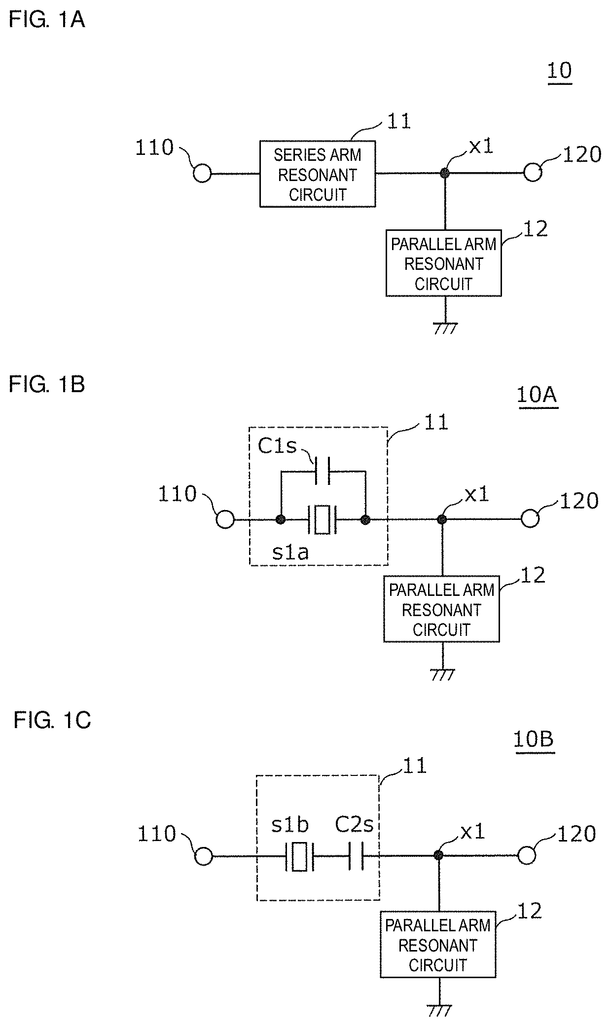
[0135]FIG. 1A is a circuit block diagram of a filter 10 according to a first preferred embodiment of the present invention. The filter 10 illustrated in FIG. 1A includes a series arm resonant circuit 11 and a parallel arm resonant circuit 12.

[0136]The series arm resonant circuit 11 is connected between an input / output terminal 110 (the first input / output terminal) and an input / output terminal 120 (the second input / output terminal).

[0137]The parallel arm resonant circuit 12 is connected to a node x1 on a path connecting the input / output terminal 110 to the input / output terminal 120 and the ground (a reference terminal).

[0138]FIG. 1B is a circuit configuration diagram of a filter 10A according to the first preferred embodiment. The filter 10A illustrated in FIG. 1B is an example of the specific circuit configuration of the filter 10. As illustrated in FIG. 1B, the filter 10A includes the series arm resonant circuit 11 and the parallel arm resonant circuit...

second preferred embodiment

[0248]Although the filter according to the first preferred embodiment includes the series arm resonant circuit including the series arm resonator and the capacitor connected in parallel to each other, a filter is described in a second preferred embodiment of the present invention, which includes a series arm resonant circuit to which a circuit element other than the series arm resonator and the capacitor is added.

2.1 Configuration of Filter 10D

[0249]FIG. 16 is a circuit configuration diagram of a filter 10D according to a second preferred embodiment. The filter 10D illustrated in FIG. 16 includes a series arm resonant circuit 11D and the parallel arm resonant circuit 12 and the series arm resonant circuit 11D includes the series arm resonator s1, a capacitor C1, and an impedance element z1. The filter 10D illustrated in FIG. 16 differs from the filter 10A according to the first preferred embodiment only in that the filter 10D includes the impedance element z1. As for the filter 10D ...

third preferred embodiment

[0314]Although the filters according to the first and second preferred embodiments each include the parallel arm resonant circuit including one parallel arm resonator, a filter is described in a third preferred embodiment of the present invention, which includes a parallel arm resonant circuit to which a circuit element other than the parallel arm resonator is added.

3.1 Configurations of Filters 10HA and 10HB

[0315]FIG. 26A is a circuit configuration diagram of a filter 10HA according to a third preferred embodiment (a seventh example). The filter 10HA illustrated in FIG. 26A includes the series arm resonant circuit 11 and a parallel arm resonant circuit 12HA. The series arm resonant circuit 11 includes the series arm resonator s1 and the capacitor C1. The parallel arm resonant circuit 12HA includes a parallel arm resonator p1 and a capacitor C3. The filter 10HA illustrated in FIG. 26A differs from the filter 10A according to the first example in the circuit configuration of the para...


PUM


Abstract

A filter includes a series arm resonant circuit connected between input/output terminals, and a parallel arm resonant circuit connected between a node on a path connecting the input/output terminals and ground. The series arm resonant circuit includes a series arm resonator having a band width ratio wider than the band width ratio of the parallel arm resonant circuit and a capacitor connected to the series arm resonator.

Description

CROSS REFERENCE TO RELATED APPLICATIONS[0001]This application claims the benefit of priority to Japanese Patent Application No. 2017-029522 filed on Feb. 20, 2017 and is a Continuation Application of PCT Application No. PCT / JP2018 / 005281 filed on Feb. 15, 2018. The entire contents of each application are hereby incorporated herein by reference.BACKGROUND OF THE INVENTION1. Field of the Invention[0002]The present invention relates to a filter apparatus including resonators, a multiplexer, a radio-frequency front end circuit, and a communication apparatus.2. Description of the Related Art[0003]Filters disposed in front end portions of mobile communication devices are required to appropriately adjust pass band widths, the sharpness of pass band ends, attenuation band widths, and so on in accordance with the combination of bands used in multimode-multiband communication.[0004]Japanese Unexamined Patent Application Publication No. 2005-260909 discloses a configuration of a surface acoust...

Claims


Application Information

Patent Timeline
IPC IPC(8): H03H9/02H03H9/25H03H9/145H03H9/64H03H9/72H01Q1/50
CPCH03H9/14541H03H9/542H03H9/6483H04B1/0458H04B1/18H01Q1/50H03H9/02866H03H9/14544H03H9/25H03H9/6489H03H9/72H04B1/40
Inventor NOSAKA, KOJI
Owner MURATA MFG CO LTD
Why Eureka
Try Eureka