Nozzle for combustors and gas turbine including the same

a technology of gas turbine and nozzle, which is applied in the direction of machines/engines, mechanical equipment, lighting and heating apparatus, etc., can solve the problems of thermal barrier coating film formed on the nozzle, damage, etc., and achieve the effect of efficient atomization of fuel

Active Publication Date: 2019-12-05
DOOSAN HEAVY IND & CONSTR CO LTD
View PDF0 Cites 6 Cited by
  • Summary
  • Abstract
  • Description
  • Claims
  • Application Information

AI Technical Summary

Benefits of technology

[0006]To solve the problem and more, an object of the present disclosure is to provide a nozzle, a combustor and a gas turbine capable of efficiently atomizing fuel.

Problems solved by technology

If the front end of the nozzle overheats, a problem may arise in that a thermal barrier coating film formed on the nozzle is damaged.

Method used


Image

  • Nozzle for combustors and gas turbine including the same
  • Nozzle for combustors and gas turbine including the same
  • Nozzle for combustors and gas turbine including the same

Examples


first embodiment

[0039]Hereinafter, a gas turbine in accordance with the present disclosure will be described.

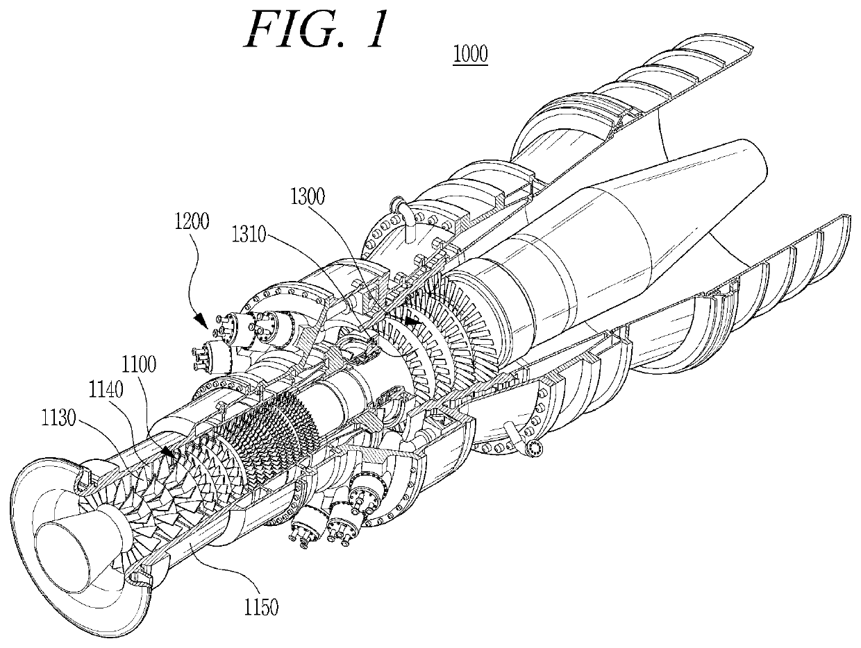
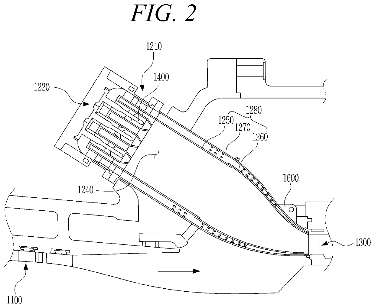
[0040]FIG. 1 is a diagram illustrating an internal structure of a gas turbine in accordance with an embodiment of the present disclosure, and FIG. 2 is a diagram illustrating a combustor of FIG. 1.

[0041]The thermodynamic cycle of the gas turbine 1000 in accordance with the present embodiment may ideally comply with the Brayton cycle. The Brayton cycle may comprise four processes including an isentropic compression (adiabatic compression) process, an isobaric heat supply process, an isentropic expansion (adiabatic expansion) process, and an isobaric heat rejection process. In other words, the gas turbine may draw air from the atmosphere, compress the air to a high pressure, combust fuel under isobaric conditions to emit thermal energy, expand this high-temperature combustion gas to convert the thermal energy of the combustion gas into kinetic energy, and thereafter discharge exhaust gas with ...

second embodiment

[0083]Hereinafter, a nozzle in accordance with the present disclosure will be described.

[0084]FIG. 8 is a sectional perspective view illustrating a nozzle 2400 in accordance with the second embodiment of the present disclosure, and FIG. 9 is a sectional view of the nozzle 2400 in accordance with the second embodiment of the present disclosure.

[0085]Referring to FIGS. 8 and 9, the structure of the nozzle 2400 in accordance with the second embodiment, except the structure of a centrifugal flow chamber 2423 in a nozzle tip 2420, is the same as that of the nozzle in accordance with the first embodiment; therefore, repetitive explanation of the same structure will be omitted.

[0086]The nozzle 2400 in accordance with the second embodiment includes a tube assembly, the nozzle tip 2420, and a heat shield cover 2430.

[0087]The nozzle tip 2420 is coupled with the tube assembly and functions to atomize and inject main fuel and pilot fuel. The heat shield cover 2430 is coupled with the outer tube...

third embodiment

[0095]Hereinafter, a nozzle in accordance with the present disclosure will be described.

[0096]FIG. 10 is a sectional perspective view illustrating a nozzle 3400 in accordance with the third embodiment of the present disclosure, and FIG. 11 is a sectional view of a front end of the nozzle 3400 in accordance with the third embodiment of the present disclosure.

[0097]Referring to FIGS. 10 and 11, the structure of the nozzle 3400 in accordance with the third embodiment, except the structure of a front-end surface 3429 of a nozzle tip 3420, is the same as that of the nozzle in accordance with the first embodiment; therefore, repetitive explanation of the same structure will be omitted.

[0098]The nozzle tip 3420 in accordance with the third embodiment is coupled with the tube assembly. An injection passage 3421 and a plurality of centrifugal flow chambers 3423 are formed in the nozzle tip 3420. The injection passage 3421 is coupled with the pilot fuel passage. The plurality of centrifugal f...


PUM


Abstract

Disclosed herein are a nozzle capable of efficiently atomizing fuel, a combustor, and a gas turbine. The nozzle for the combustor includes a tube assembly including an air passage through which air moves, a main fuel passage disposed inside the air passage so that main fuel moves through the main fuel passage, and a pilot fuel passage disposed inside the main fuel passage so that pilot fuel moves through the pilot fuel passage as well as a nozzle tip configured to eject the pilot fuel and the main fuel, where the nozzle tip includes an injection passage coupled with the pilot fuel passage and a plurality of centrifugal flow chambers disposed outside the injection passage and communicating with the main fuel passage.

Description

CROSS-REFERENCE TO RELATED APPLICATION[0001]This application claims priority to Korean Patent Application No. 10-2018-0062021, filed on May 30, 2018, the disclosure of which is incorporated herein by reference in its entirety.BACKGROUND OF THE DISCLOSUREField of the Disclosure[0002]Exemplary embodiments of the present disclosure relate to a nozzle for combustors and a gas turbine including the combustor.Description of the Related Art[0003]A gas turbine is a power engine configured to mix fuel with air compressed by a compressor, combust the mixture of the fuel and the compressed air, and rotate a turbine using high-temperature gas generated by the combustion. The gas turbine is used to drive a generator, an aircraft, a vessel, a train, and so forth.[0004]Generally, the gas turbine includes a compressor, a combustor, and a turbine. The compressor draws external air thereinto, compresses the air, and then transmits it to the combustor. The air compressed by the compressor enters a hig...

Claims


Application Information

Patent Timeline
Patent Type & Authority Applications(United States)
IPC IPC(8): F02C7/18F01D25/12F02C7/22F23R3/04
CPCF01D25/12F23R3/04F23R3/283F02C7/18F02C7/22F05D2240/36F05D2260/20F23D11/383Y02T50/60F05D2240/35F23R3/16F23R3/28
Inventor MYATLEV, ALEXANDERJEONG, HANJINSHERSHNYOV, BORYS
Owner DOOSAN HEAVY IND & CONSTR CO LTD
Why Eureka
Try Eureka