Power supply circuit for biological signal measurement circuit and biological signal measuring apparatus

Active Publication Date: 2019-12-05
SIMPLEX QUANTUM
View PDF0 Cites 2 Cited by
  • Summary
  • Abstract
  • Description
  • Claims
  • Application Information

AI Technical Summary

Benefits of technology

The present invention provides a power supply circuit and a biological signal measuring apparatus that can isolate the measurement system and power supply system with a simple configuration. This improves convenience by reducing the time needed to charge.

Problems solved by technology

Those electric signals are extremely weak.
However, there are not a few technical problems that should be solved in configuring the electrocardiograph as a portable terminal or a stationary small terminal.
One of the technical problems is prevention of an electric shock of a person as a measurement target of biological signals.
However, to transmit the electric power via the transformer, it is necessary to convert a direct current on a primary side into a high-frequency alternating current, which incurs a lot of induction noise in the conversion process.
Therefore, use of the insulated transformer is undesirable.
The insulated transformer is an expensive component and needs the power conversion circuit described above.
However, when a general secondary battery is used as a power supply of the measuring apparatus, the measuring apparatus has problems in that the apparatus cannot be used during a charging period, and it is difficult to make maintenance unnecessary for a long period due to the limitation of the number of times of charging of the secondary battery.

Method used


Image

  • Power supply circuit for biological signal measurement circuit and biological signal measuring apparatus
  • Power supply circuit for biological signal measurement circuit and biological signal measuring apparatus
  • Power supply circuit for biological signal measurement circuit and biological signal measuring apparatus

Examples


Embodiment Construction

[0026]In describing embodiments illustrated in the drawings, specific terminology is employed for the sake of clarity. However, the disclosure of the present specification is not intended to be limited to the specific terminology so selected and it is to be understood that each specific element includes all technical equivalents that have a similar function, operate in a similar manner, and achieve a similar result.

[0027]As used herein, the singular forms “a”, “an”, and “the” are intended to include the plural forms as well, unless the context clearly indicates otherwise.

[0028]Referring to the drawings, wherein like reference numerals designate identical or corresponding parts throughout the several views, embodiments of the present disclosure are described below.

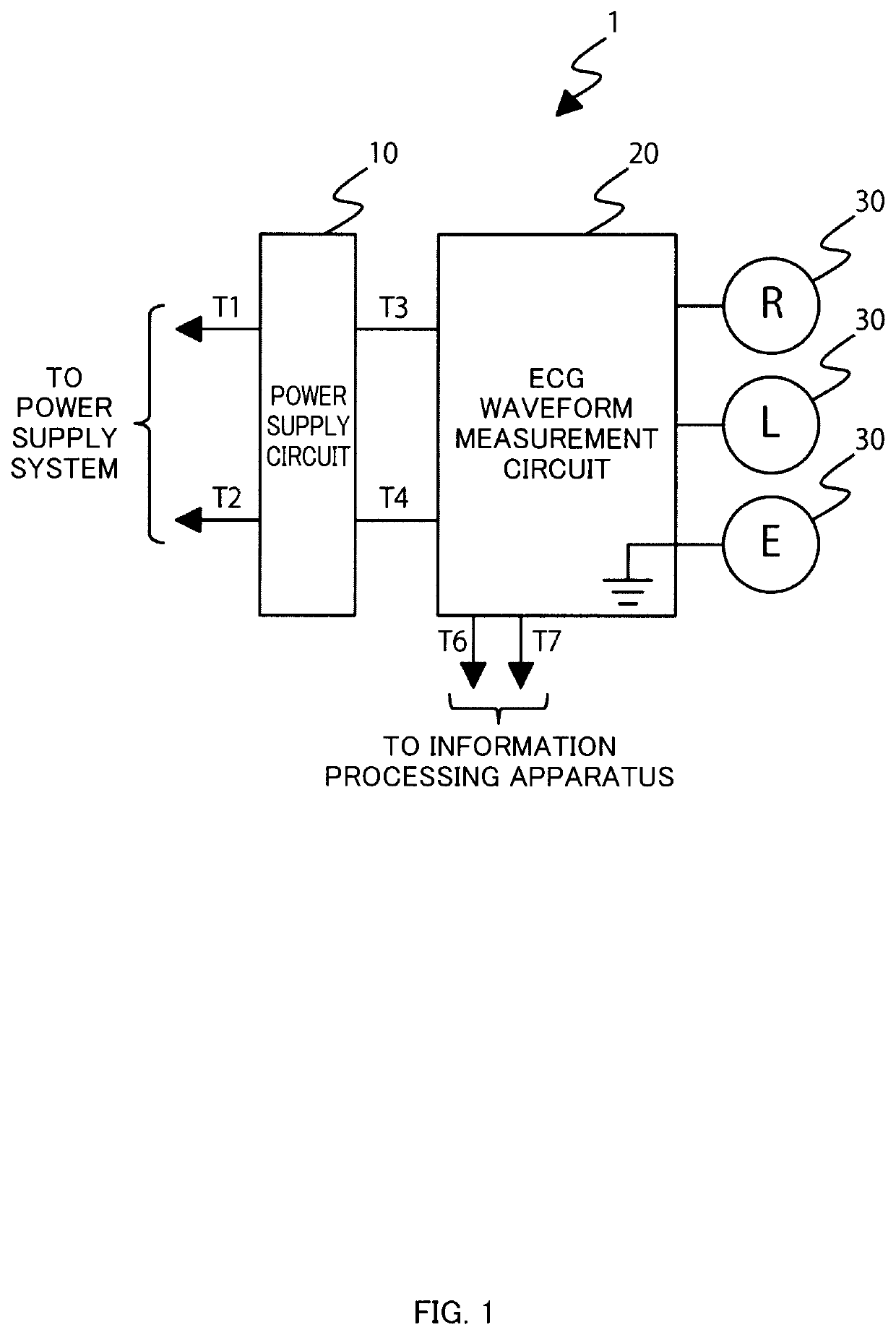
[0029]In FIG. 1, a schematic configuration example of an electrocardiographic waveform measuring apparatus according to the embodiment of the present invention is schematically shown. The present invention can be applied to...


PUM


Abstract

Provided is a power supply circuit that supplies electric power to a biological signal measurement circuit configured to detect, with an electrode set in contact with a human body, a biological signal which is a weak electric signal emitted by the human body. The power supply circuit includes a capacitance element accumulating the electric power, and a circuit switch coupled between the capacitance element and an external power supply for supplying electric power to the capacitance element, and configured to switch, not through a state where the external power supply and the biological signal measurement circuit are electrically coupled, a first state where the capacitance element establishes electrical continuity with the external power supply and is enabled to be charged, and a second state where the capacitance element establishes electrical continuity with the biological signal measurement circuit and is enabled to supply power to the biological signal measurement circuit.

Description

BACKGROUNDTechnical Field[0001]The present invention relates to a power supply circuit for a biological signal measurement circuit and a biological signal measuring apparatus.Related Art[0002]Electrocardiogram (ECG), electromyogram (EMG), and electroencephalogram (EEG) are well known as biological signals, which are electric signals obtained from an organism. Those electric signals are extremely weak. Usually, the electric signals are measured with multiple electrodes set in direct contact with a human body.[0003]Large measuring apparatuses for medical tests have been present. However, with recent advancement in a size reduction and power saving of the measuring apparatuses, battery-driven small portable terminals have been also used to measure biological signals conveniently. These small portable terminals mainly use a rechargeable secondary battery as a power supply and wireless transmission such as Bluetooth (registered trademark) as data transmitting means.[0004]In addition to e...

Claims


Application Information

Patent Timeline
IPC IPC(8): H02J7/00A61B5/0408
CPCH02J7/0068A61B2560/0214H02J7/345A61B5/0408H02J2007/0049H02J7/0047A61B5/25H02J2310/23H02J7/0049A61B5/308
Inventor NAKAMURA, HIROSHIHAMADA, YUJI
Owner SIMPLEX QUANTUM
Why Eureka
Try Eureka