Supercharge Your Innovation With Domain-Expert AI Agents!

Image processing apparatus, radiography system, image processing method, and image processing program

a radiography system and image processing technology, applied in the field of image processing apparatus, radiography system, image processing method, image processing program, can solve the problem that the radiographic image of the desired quality cannot be obtained in the main imaging field, and achieve the effect of improving the quality of the imag

Active Publication Date: 2019-12-12
FUJIFILM CORP
View PDF0 Cites 0 Cited by
  • Summary
  • Abstract
  • Description
  • Claims
  • Application Information

AI Technical Summary

Benefits of technology

The patent text describes an image processing apparatus that can create high-quality radiographic images. It does this by analyzing the soft tissue in the image and determining the percentage of muscle and fat in the composition. When the percentage of muscle is higher, the apparatus reduces the second energy in the image to achieve the desired quality. This technique improves the accuracy and reliability of radiographic images.

Problems solved by technology

Therefore, in some cases, a radiographic image with desired quality is not obtained in the main imaging.

Method used


Image

  • Image processing apparatus, radiography system, image processing method, and image processing program
  • Image processing apparatus, radiography system, image processing method, and image processing program
  • Image processing apparatus, radiography system, image processing method, and image processing program

Examples


first embodiment

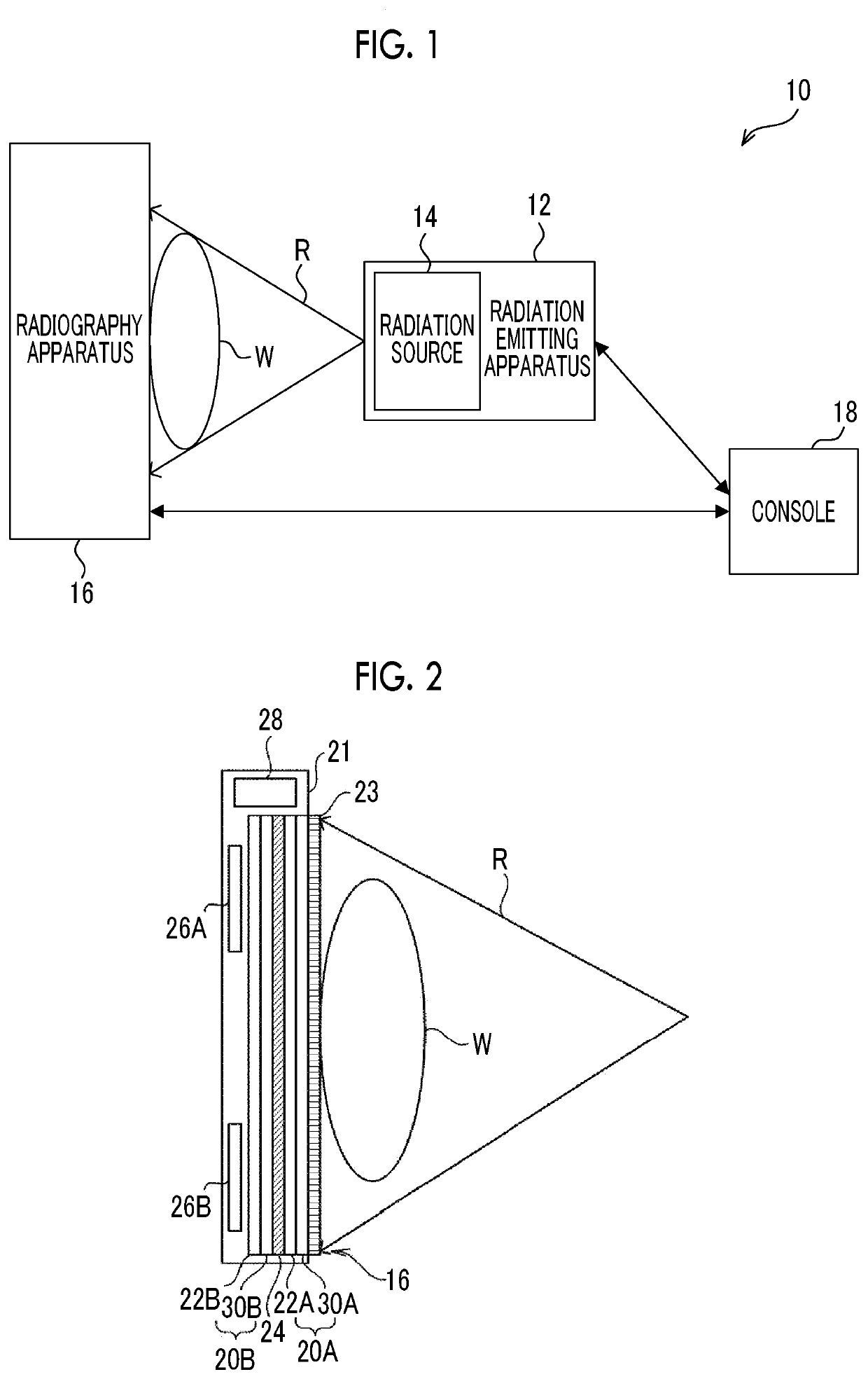
[0049]First, the configuration of a radiography system 10 according to this embodiment will be described with reference to FIG. 1. As illustrated in FIG. 1, the radiography system 10 includes a radiation emitting apparatus 12, a radiography apparatus 16, and a console 18. The console 18 is an example of an image processing apparatus according to the present disclosure. In addition, for example, the radiography system 10 according to this embodiment captures a radiographic image of a subject W in a standing state.

[0050]The radiation emitting apparatus 12 according to this embodiment includes a radiation source 14 that irradiates a subject W, which is an example of an imaging target, with radiation R such as X-rays. The radiation emitting apparatus 12 according to this embodiment emits the radiation R with a cone-beam shape. An example of the radiation emitting apparatus 12 is a treatment cart. A method for commanding the radiation emitting apparatus 12 to emit the radiation R is not ...

second embodiment

[0127]Hereinafter, a second embodiment of the technology according to the present disclosure will be described in detail. In addition, since the configuration of a radiography system 10 according to this embodiment is the same as that in the first embodiment except for information stored in the storage unit 86 of the console 18 (see FIGS. 1 to 4), the description thereof will not be repeated here. Further, components having the same functions as those in the first embodiment are denoted by the same reference numerals and the description thereof will not be repeated.

[0128]As in an example illustrated in FIG. 14, the storage unit 86 of the console 18 according to this embodiment further stores scattered ray correction data 95 for correcting scattered ray components which will be described below.

[0129]As described above, a predetermined amount of scattered rays is removed by the grid 23. However, components (hereinafter, “scattered ray components”) caused by the scattered rays which ha...


PUM


Abstract

A CPU functions as an acquisition unit and a derivation unit. The acquisition unit acquires a first radiographic image and a second radiographic image respectively generated by a first radiation detector and a second radiation detectors which are irradiated with radiation with first energy emitted from a radiation source in preliminary imaging before main imaging from a radiography apparatus in which the first and second radiation detectors are arranged in a direction in which the radiation is emitted. The derivation unit derives the composition of a soft part of a subject, using the first and second radiographic images acquired by the acquisition unit, and derives second energy of the radiation emitted from the radiation source in the main imaging according to the derived composition of the soft part.

Description

CROSS-REFERENCE TO RELATED APPLICATION[0001]This application claims priority from Japanese Patent Application No. 2018-110390, filed on Apr. 1, 2016, the disclosure of which is incorporated by reference herein in its entirety.BACKGROUNDField of the Invention[0002]The present disclosure relates to an image processing apparatus, a radiography system, an image processing method, and an image processing program.Related Art[0003]In recent years, a technique has been disclosed which performs preliminary imaging before main imaging and determines imaging conditions in the main imaging on the basis of the result of the preliminary imaging in a case in which a radiographic image of a subject is captured by a radiography apparatus (for example, see JP2018-023769A).[0004]However, even in a case in which the imaging conditions are the same, the quality of a radiographic image captured by a radiography apparatus may vary depending on the subject. For example, since the quality of radiation trans...

Claims


Application Information

Patent Timeline
Patent Type & Authority Applications(United States)
IPC IPC(8): A61B6/00
CPCA61B6/5217A61B6/505A61B6/482A61B6/50A61B6/5282A61B6/488A61B6/5205A61B6/542A61B6/544
Inventor ODA, YASUFUMI
Owner FUJIFILM CORP
Features
  • R&D
  • Intellectual Property
  • Life Sciences
  • Materials
  • Tech Scout
  • Unparalleled Data Quality
  • Higher Quality Content
  • 60% Fewer Hallucinations
Learn More