
Shrinking interface layers

Inactive Publication Date: 2019-12-12
DESKTOP METAL INC
View PDF0 Cites 15 Cited by
  • Summary
  • Abstract
  • Description
  • Claims
  • Application Information

AI Technical Summary

Benefits of technology

The present invention relates to a shrinkable interface composition for the printing and thermal processing of a three-dimensional printed powder part. The interface composition is designed to allow for a controlled shrinkage of the part during sintering, while also allowing for the separation of the part from its surrounding metal geometry. The interface composition can be made up of ceramic powder and metal powder, and it can be constrained or trapped by the metal geometry. The resultant shrinkage of the interface layer is between about 3% and about 27% by volume, and it remains substantially free-flowing after sintering. The invention also relates to a method for printing and thermal processing the powder part using the interface composition.

Problems solved by technology

Metal parts are very soft and weak at their sintering temperatures, and if the ceramic cannot allow for the shrinkage of the part, then cracks or distortions are likely to occur.
If the support powder restricts the relative sliding motion of the metal part, then warping or cracking can occur along the interface.

Method used


Image

  • Shrinking interface layers
  • Shrinking interface layers
  • Shrinking interface layers

Examples


Embodiment Construction

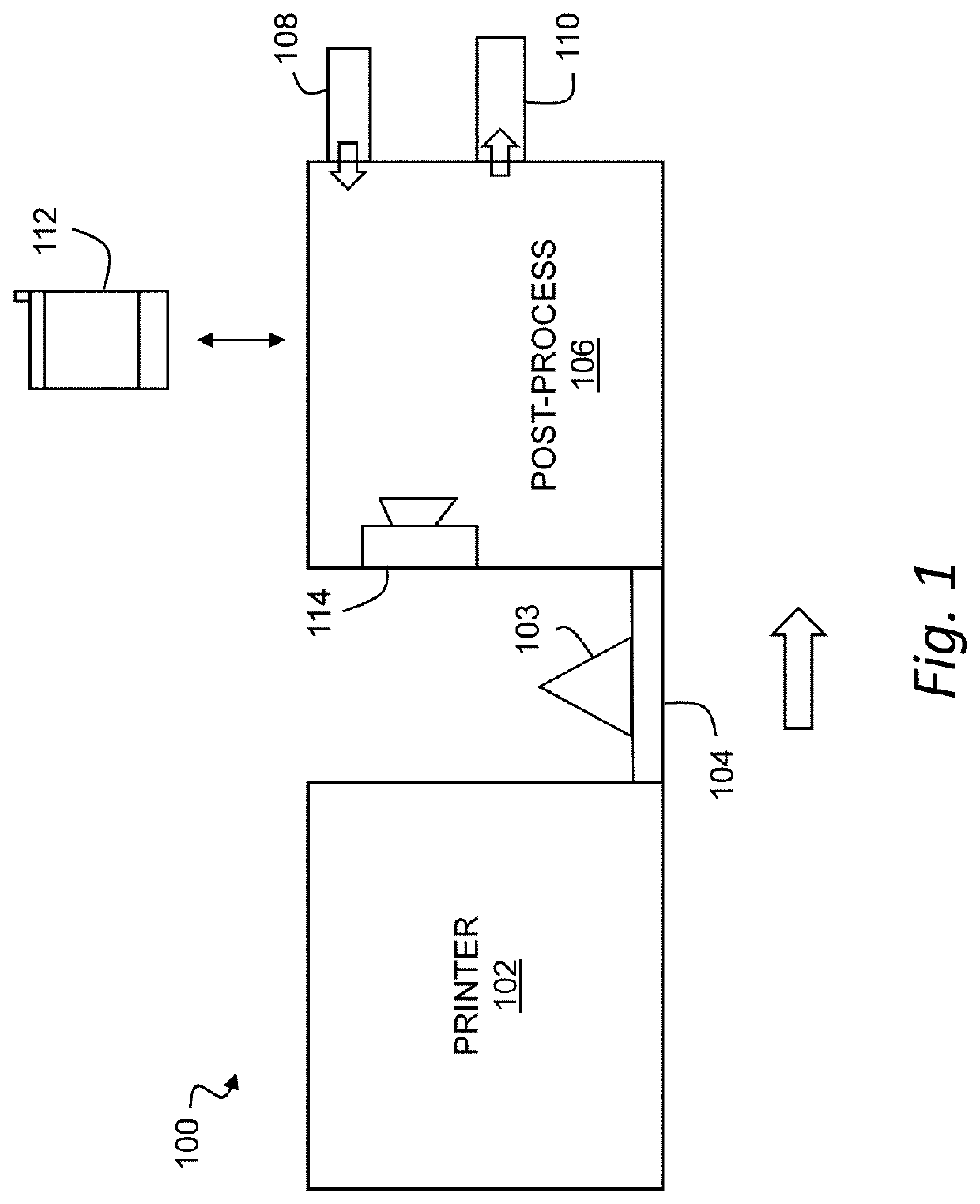
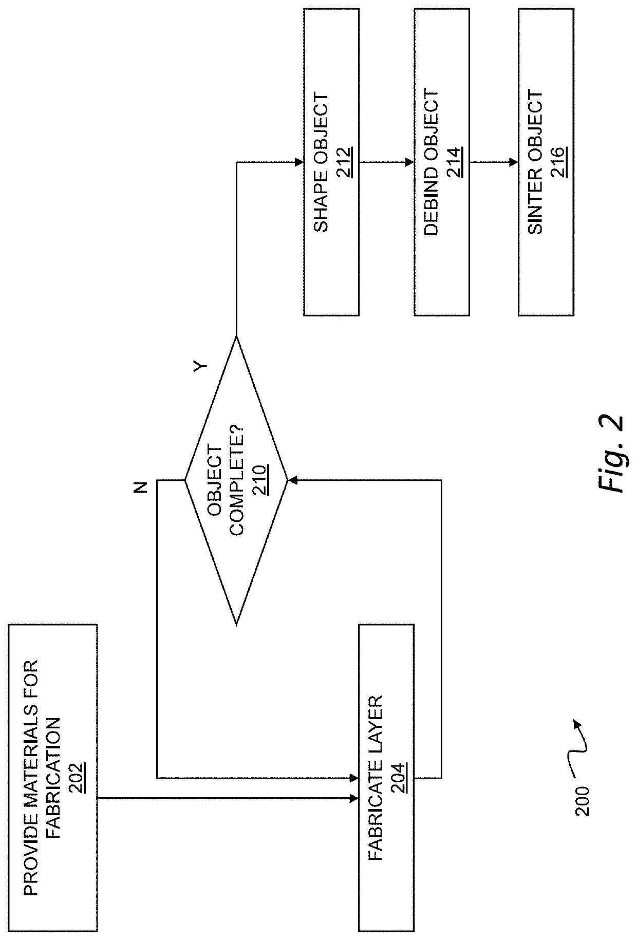
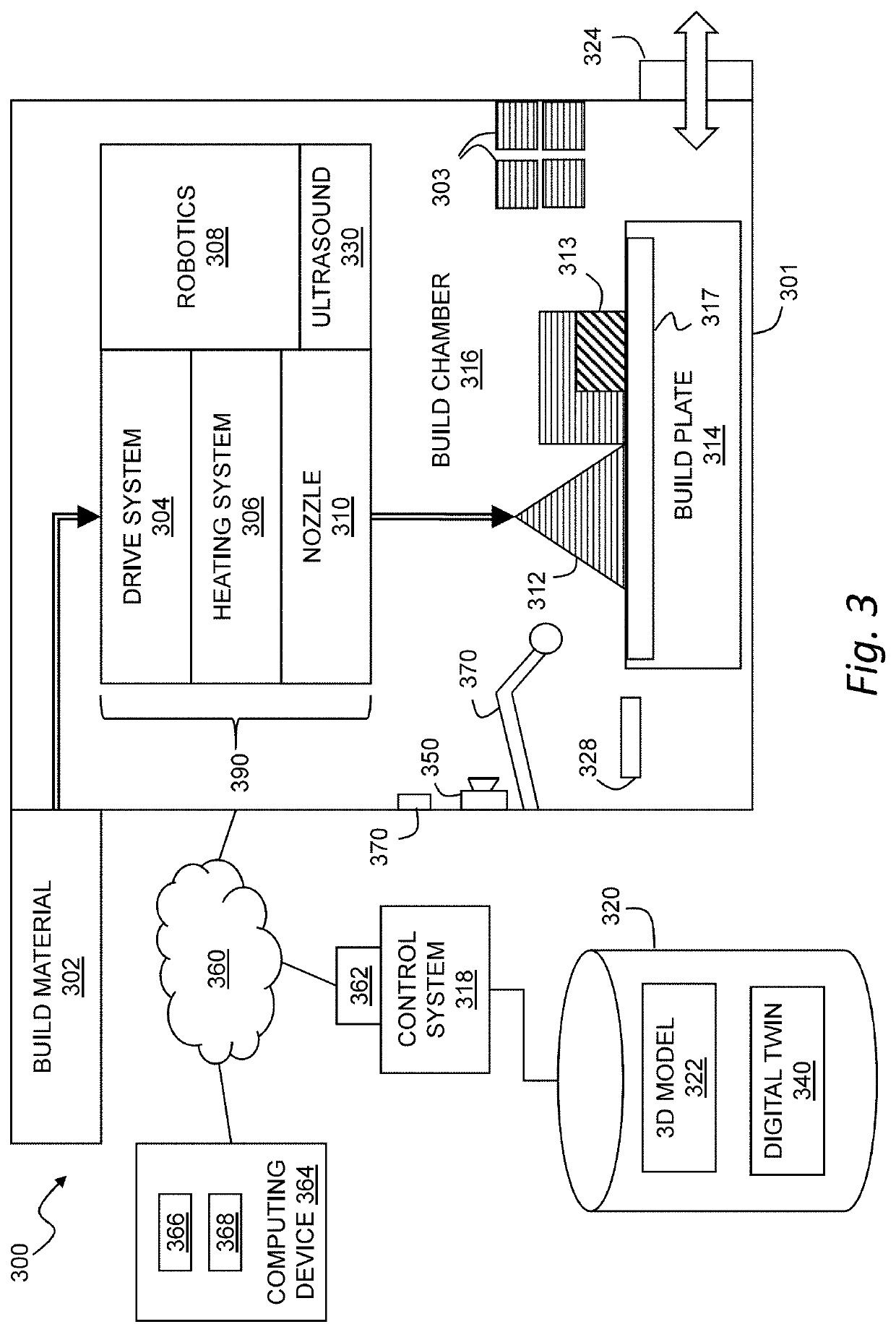
[0081]In the following detailed description, reference is made to the accompanying drawings which form a part hereof, and in which is shown by way of illustration specific embodiments in which the invention may be practiced. These embodiments are described in sufficient detail to enable those skilled in the art to practice the invention, and it is to be understood that the embodiments may be combined, or that other embodiments may be utilized and that structural and logical changes may be made without departing from the spirit and scope of the present invention. The following detailed description is, therefore, not to be taken in a limiting sense.

[0082]In further embodiments the present invention relates to a three-dimensionally printed article of manufacture prepared using the system of the present invention. In yet other embodiments the present invention relates to systems, including software, for three-dimensionally printing the articles and interface layers.

[0083]There are numer...


PUM

PropertyMeasurementUnit
Shrinkageaaaaaaaaaa
Fractionaaaaaaaaaa
Fractionaaaaaaaaaa

Abstract

The present invention relates to a shrinking interface composition that allows for the accommodation of sintering shrinkage between two or more areas or sections of a three-dimensionally printed part and / or support structures for the part. The interface composition, which can be in the form of an interface layer, is used to prevent the fusing of the sections, parts or support structures to each other.

Description

FIELD OF THE INVENTION[0001]The present invention relates to a shrinking interface layer that allows for the accommodation of sintering shrinkage between two or more areas or sections of a three-dimensionally (3-D) printed powdered part, between two or more printed powder parts, between one or more support structures and one or more powder parts, or between two or more support structures. The support structures can be used to prevent warpage or slumping during sintering of the powder part. The interface layer can also be used to prevent the sticking of the parts and / or support structures to each other. Both the powdered part and the support structure are comprised of substantially similar powdered metal or other materials that shrink and densify as heated. The interface layer comprises a non-sintering powdered ceramic material that remains at least partially free flowing during and after sintering. In this invention the support material is made to shrink by selecting materials that ...

Claims


Application Information

Patent Timeline
IPC IPC(8): B22F3/105B28B1/00B22F1/05B22F1/10
CPCB33Y70/00B33Y30/00B28B1/001B33Y10/00B22F3/1055B22F2003/1058B22F3/10B22F3/1021B22F7/064B22F2203/05B22F2998/10B22F2999/00B28B1/00B29C64/40B29C64/10B29C64/188Y02P10/25B22F1/05B22F1/10B22F10/14B22F10/12B22F10/18B22F10/28B22F10/43B33Y40/20B22F10/40B22F3/20
Inventor KERNAN, BRIAN DANIELGIBSON, MICHAEL ANDREWBARBATI, ALEXANDER C.
Owner DESKTOP METAL INC
Learn More