Increased durability linear actuator

Active Publication Date: 2019-12-12
IFIT INC
View PDF0 Cites 28 Cited by
  • Summary
  • Abstract
  • Description
  • Claims
  • Application Information

AI Technical Summary

Benefits of technology

[0009]This Summary is provided to introduce a selection of concepts in a simplified form that are further described below in the Detailed Description. This Summary is not inten

Problems solved by technology

Sideloading, or the application of a force in a direction perpendicular to the longitudinal axis of the shaft, causes premature failure of the thrust bearing

Method used


Image

  • Increased durability linear actuator
  • Increased durability linear actuator
  • Increased durability linear actuator

Examples


Embodiment Construction

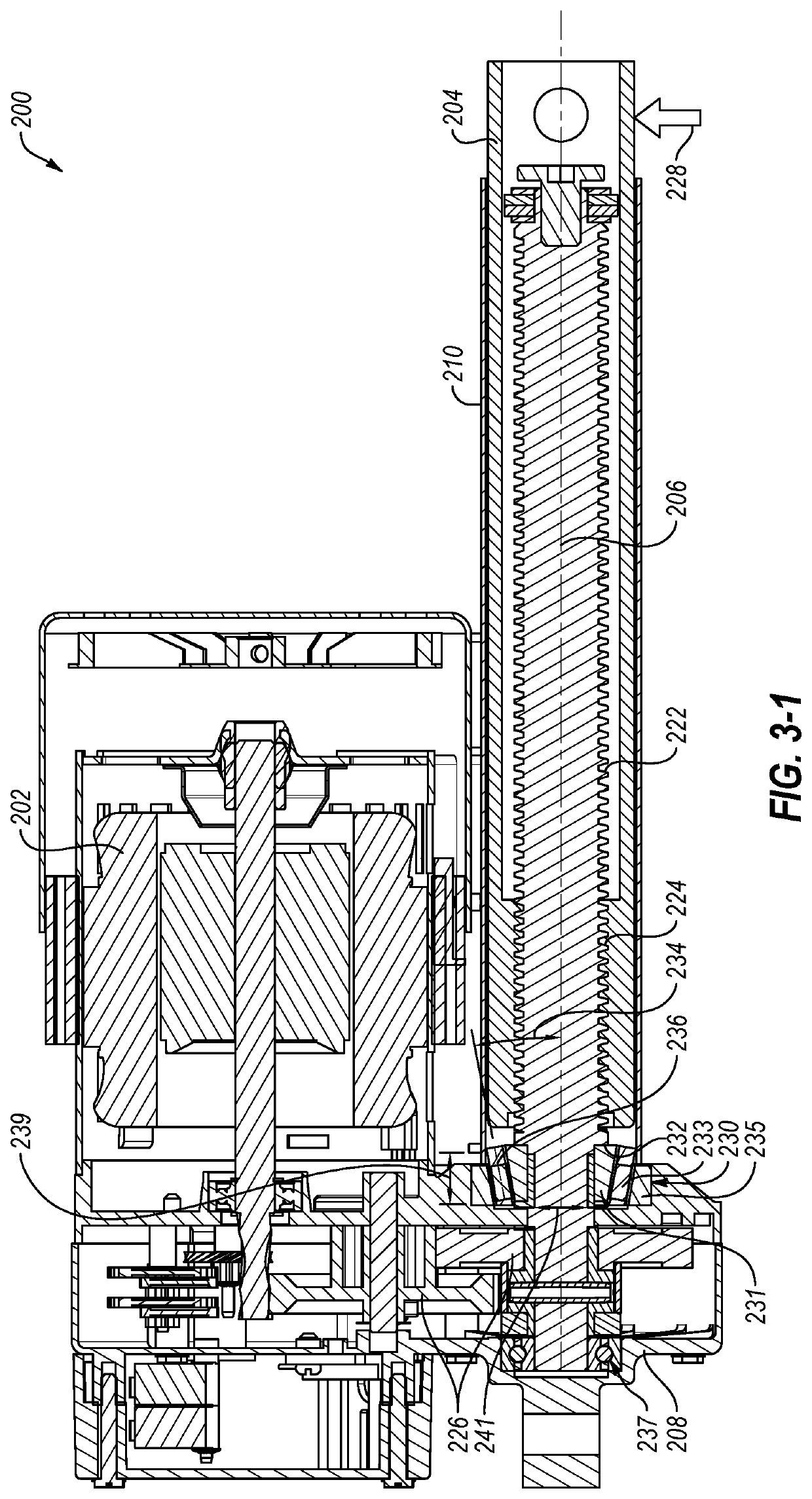
[0020]In some embodiments of a linear actuator according to the present disclosure, an actuator may include a tapered roller bearing supporting a shaft to reinforce the shaft against sideloading. For example, a conventional linear actuator has a bushing positioned at a base of a shaft to support the shaft against axial loads applied to the shaft. The bushing or other axial bearings may provide axial support but may wear prematurely when the linear actuator is exposed to lateral forces applied to the shaft.

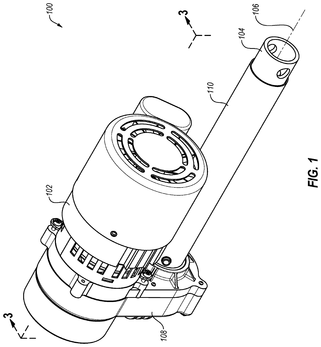
[0021]FIG. 1 is a perspective view of a linear actuator 100, according to the present disclosure. The linear actuator 100 includes a motor 102 configured to move a shaft 104 axially along a longitudinal axis 106 of the shaft 104. The motor 102 is connected to the shaft 104 through a casing 108 and a sleeve 110. The casing 108 may contain one or more gears, belts, cables, or other torque transmission devices to transfer torque from the motor 102 to an acme screw in the sleeve 110. T...


PUM


Abstract

A linear actuator includes a motor, a shaft, and a casing. The shaft has a longitudinal axis, and the shaft is moveable along the longitudinal axis by the motor. The casing supports the motor and the shaft with a tapered roller bearing positioned between at least a portion of the shaft and a portion of the casing.

Description

CROSS-REFERENCE TO RELATED APPLICATIONS[0001]This application claims priority to provisional patent application No. 62 / 683,331 entitled “INCREASED DURABILITY LINEAR ACTUATOR” filed Jun. 11, 2018, which application is herein incorporated by reference for all that it discloses.BACKGROUNDTechnical Field[0002]This disclosure generally relates to linear actuators. More particularly, this disclosure generally relates to linear actuators used to modify the incline of another platform.Background and Relevant Art[0003]Conventional linear actuators include a moveable shaft that is supported by thrust bearings. The thrust bearings support the shaft against axial loads when the shaft applies a force to another object. Linear actuators with shafts driven by acme screws have a rotary thrust bearing that allows the acme screw to rotate while the shaft is under an axial compression force.[0004]Sideloading, or the application of a force in a direction perpendicular to the longitudinal axis of the sh...

Claims


Application Information

Patent Timeline
IPC IPC(8): F16H25/20A63B22/02A63B22/06
CPCF16H2025/2037F16H25/20A63B22/0664A63B22/0605A63B22/02F16H2025/2031A63B2225/093F16H2025/2081F16H2025/209A63B2225/09F16H25/2021
Inventor BUCHANAN, DALE ALAN
Owner IFIT INC
Why Eureka
Try Eureka