Pressure sensor

Active Publication Date: 2019-12-12
TAIWAN ALPHA ELECTRONICS
View PDF0 Cites 1 Cited by
  • Summary
  • Abstract
  • Description
  • Claims
  • Application Information

AI Technical Summary

Benefits of technology

The present invention provides a pressure sensor with increased sensitivity at high pressures by arranging spacers and finger circuits on the sensor circuit. By arranging the finger circuits in a staggered manner with different widths and spacing, a denser arrangement is assigned for the finger circuits on the central sensing region and a less dense arrangement is assigned for those on the outer sensing regions. This allows for a higher variation percentage of the pressure sensor for high-pressure testing while still keeping the sensitivity high.

Problems solved by technology

Namely, the applicable range of the conventional pressure sensor is limited.

Method used


Image

  • Pressure sensor
  • Pressure sensor
  • Pressure sensor

Examples


first embodiment

[0053]In practical applications, as the pressure sensor 100 of this first embodiment is introduced to perform testing under a pressure range from 2 bar to 6 bar, the corresponding variation percentage would be about 58.4% (computed by (Pressure detected at 2 bar−Pressure detected at 6 bar) / (Pressure detected at 2 bar)). For testing under the pressure within 4˜8 bar, the variation percentage would be about 36.5%.

[0054]Referring now to FIG. 7, relative position relationships between sensor circuits and spacers of a second embodiment of the pressure sensor in accordance with the present invention are demonstrated schematically and planarly. As shown, in this embodiment, an inner spacer 3a is used to replace the inner spacer 3 of the aforesaid first embodiment. Similar to the aforesaid inner spacer 3, this inner spacer 3a has a first-end portion 31a, a second-end portion 32a, a first lateral portion 33a and a second lateral portion 34a. The first-end portion 31a, the second-end portion ...

second embodiment

[0055]In practical applications, as the pressure sensor of this second embodiment is introduced to perform testing under a pressure range from 2 bar to 6 bar, the corresponding variation percentage would be about 53.5% (computed by (Pressure detected at 2 bar−Pressure detected at 6 bar) / (Pressure detected at 2 bar)). For testing under the pressure within 4˜8 bar, the variation percentage would be about 29.9%.

[0056]Referring now to FIG. 8, relative position relationships between sensor circuits and spacers of a third embodiment of the pressure sensor in accordance with the present invention are demonstrated schematically and planarly. As shown, in this embodiment, an inner spacer 3b is used to replace the inner spacer 3b of the aforesaid second embodiment. Similar to the aforesaid inner spacer 3a, this inner spacer 3b has a first-end portion 31b, a second-end portion 32b, a first lateral portion 33b and a second lateral portion 34b. The first-end portion 31b, the second-end portion 3...

third embodiment

[0057]In practical applications, as the pressure sensor of this third embodiment is introduced to perform testing under a pressure range from 2 bar to 6 bar, the corresponding variation percentage would be about 57% (computed by (Pressure detected at 2 bar−Pressure detected at 6 bar) / (Pressure detected at 2 bar)). For testing under the pressure within 4˜8 bar, the variation percentage would be about 32%.

[0058]Refer now to FIG. 9 to FIG. 11; where FIG. 9 is a schematic exploded view of a fourth embodiment of the pressure sensor invention accordance with the present invention, FIG. 10 is another view of FIG. 9, and FIG. 11 demonstrates schematically and planarly relative position relationships between the sensor circuits and the spacers of the fourth embodiment of the pressure sensor of FIG. 9.

[0059]As shown, in this embodiment, a pressure sensor 100c is largely resembled to the pressure sensor 100 of the first embodiment, and the major difference in between is that, in the pressure s...


PUM


Abstract

A pressure sensor includes a conductive substrate, a ring-shaped spacer, an inner spacer and a sensing circuit substrate. The conductive substrate includes a conductive-substrate body and a conductive layer. The conductive layer is disposed on the conductive-substrate body. The ring-shaped spacer and the inner spacer are disposed on the conductive-substrate body. The sensing-circuit substrate, disposed on the ring-shaped spacer and the inner spacer, includes a circuit-substrate body, a first sensing circuit and a second sensing circuit. The first sensing circuit and the second sensing circuit are disposed on opposing sides of the circuit-substrate body, and a priority of first finger circuits of the first sensing circuit and a priority of second finger circuits of the second sensing circuit are interlaced. The first sensing circuit and the second sensing circuit are densely arranged at the center of the conductive layer and less densely arranged on both sides of the conductive layer.

Description

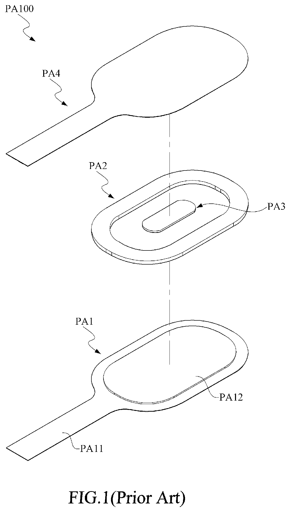
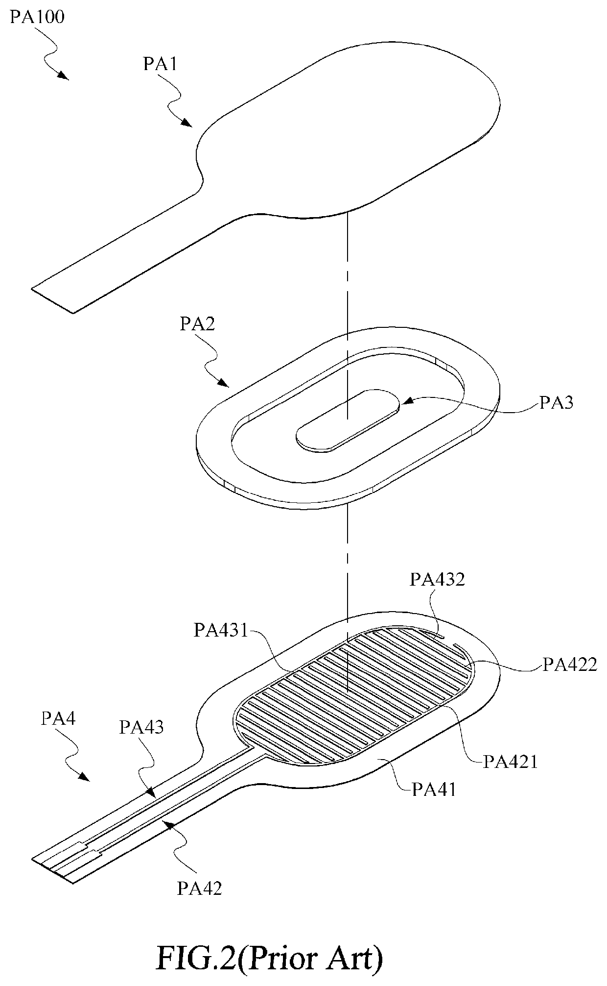
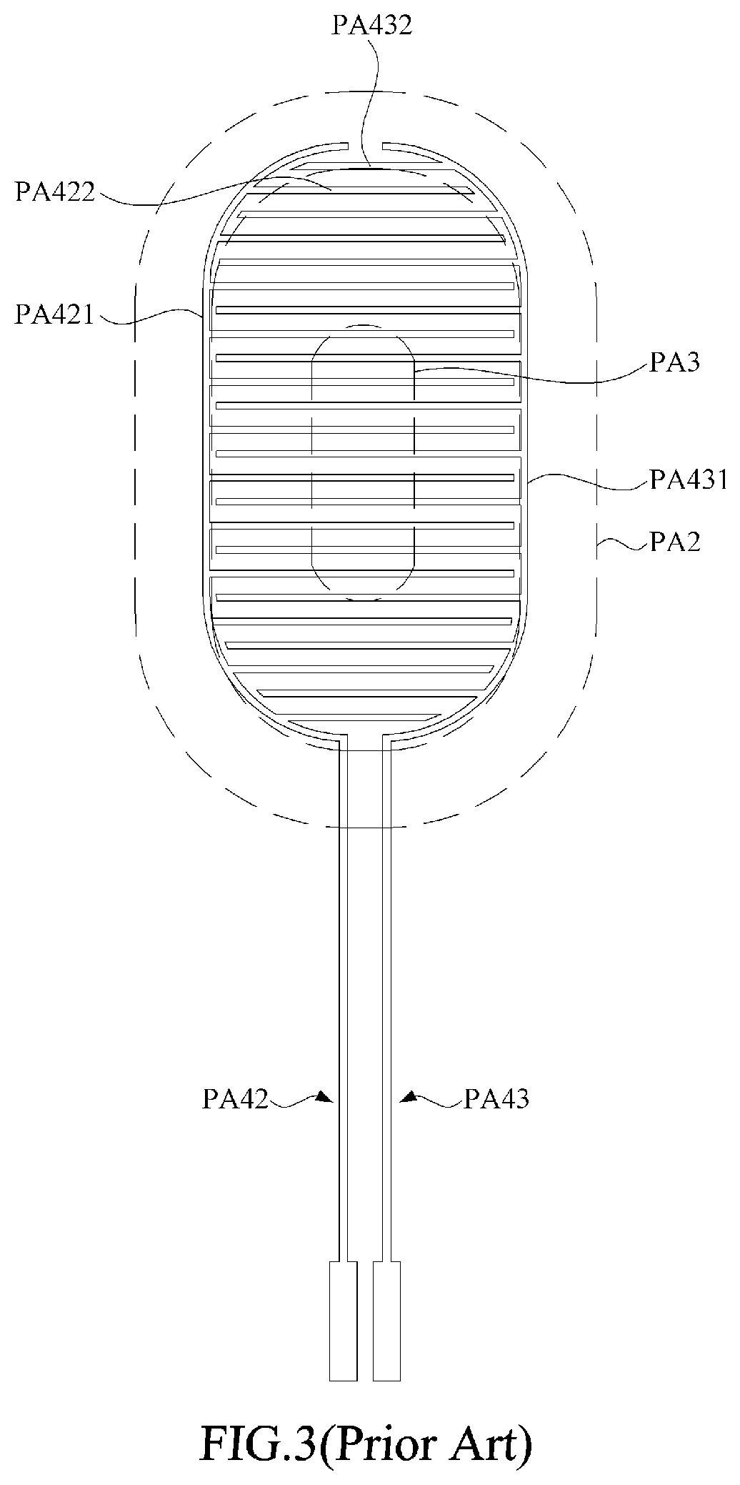
[0001]This application claims the benefit of Taiwan Patent Application Serial No. 107119878, filed Jun. 8, 2018, the subject matter of which is incorporated herein by reference.BACKGROUND OF THE INVENTION(1) Field of the Invention[0002]The invention relates to a pressure sensor, and more particularly to the pressure sensor that introduces a central sensing region formulated by a predetermined arrangement of finger circuits and spacers to enhance variation percentages under high pressures.(2) Description of the Prior Art[0003]Generally speaking, in order to inspect whether or not forcing upon the user during an exercise can distribute uniformly, or whether or not the forcing is concentrated at a particular spot, a pressure sensor is usually applied for detection. For example, in the case that distribution of forcing upon the feet of a user or a runner up is detected, a plurality of pressure sensors are arranged to the shoe pads, so the a plurality of application spots between the fee...

Claims


Application Information

Patent Timeline
IPC IPC(8): G01L1/20H05K1/14H05K1/11H05K1/03G01D21/02
CPCG01L1/205H05K2201/042H05K1/144H05K2201/10151G01D21/02H05K2201/09209H05K1/03H05K1/111G01L1/20
Inventor HUANG, TZU-HSUANLIU, WEI-LIANGCHAN, HUANG-CHAO
Owner TAIWAN ALPHA ELECTRONICS
Why Eureka
Try Eureka