All-reflective solar coronagraph sensor and thermal control subsystem

a solar coronagraph and sensor technology, applied in the field of all-reflective solar coronagraph sensor and thermal control subsystem, can solve the problems of significant image quality degradation, unsuitability for intended purposes, and difficult to see objects close to solar lines of sight (e.g., near the sun) for long periods of tim

Active Publication Date: 2019-12-12
RAYTHEON CO
View PDF0 Cites 0 Cited by
  • Summary
  • Abstract
  • Description
  • Claims
  • Application Information

AI Technical Summary

Benefits of technology

[0003]Aspects and embodiments are directed to a coronagraph optical system that includes an all-reflective optical path and a dynamically controllable solar rejection optical component (

Problems solved by technology

Sensing objects close to a solar line of sight (e.g., near the Sun) with a wide field of view and for long periods of time is problematic because conventional telescope optical systems cannot tolerate the extreme solar thermal load on components of the system.
As a result,

Method used


Image

  • All-reflective solar coronagraph sensor and thermal control subsystem
  • All-reflective solar coronagraph sensor and thermal control subsystem
  • All-reflective solar coronagraph sensor and thermal control subsystem

Examples


Embodiment Construction

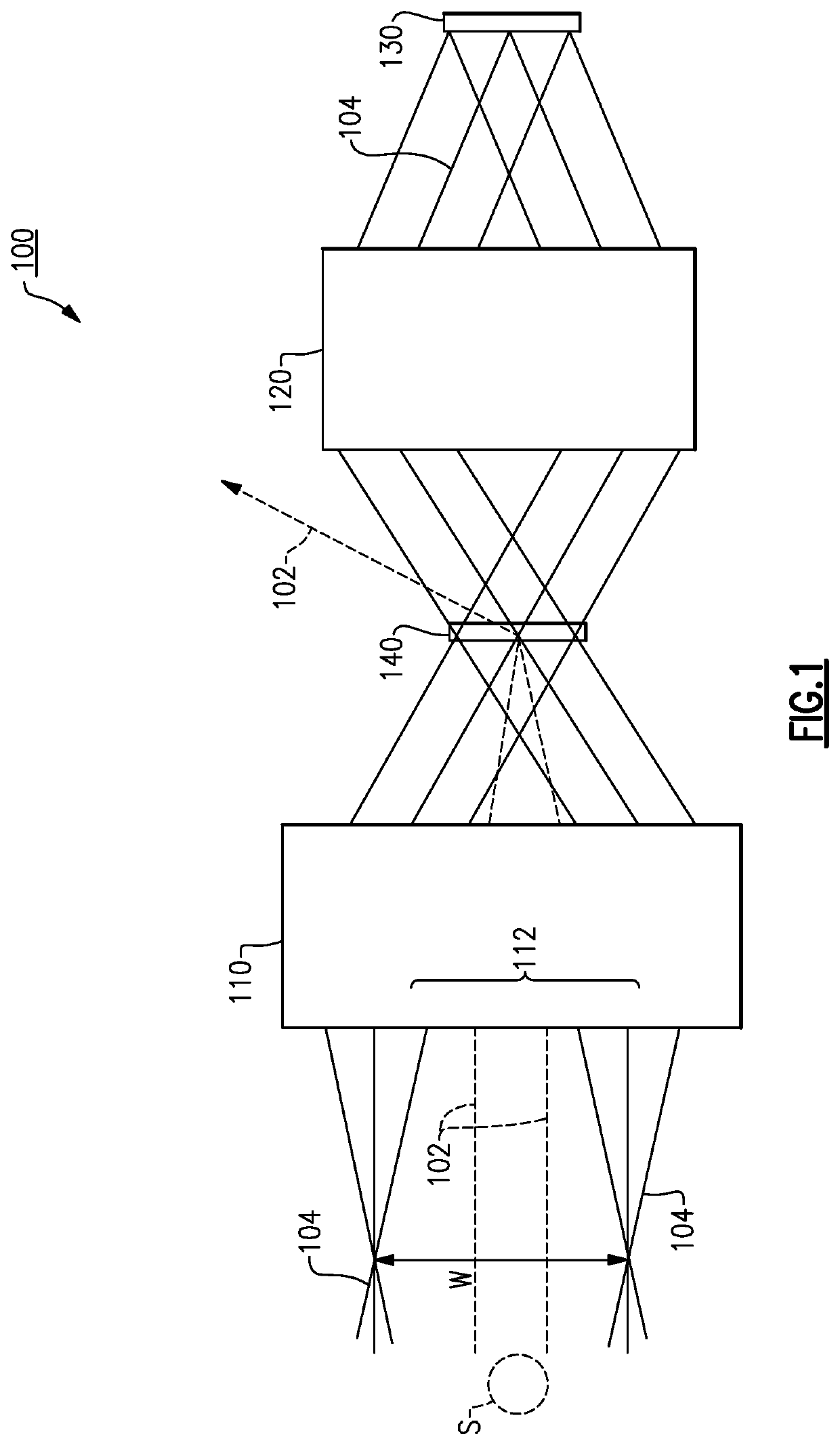
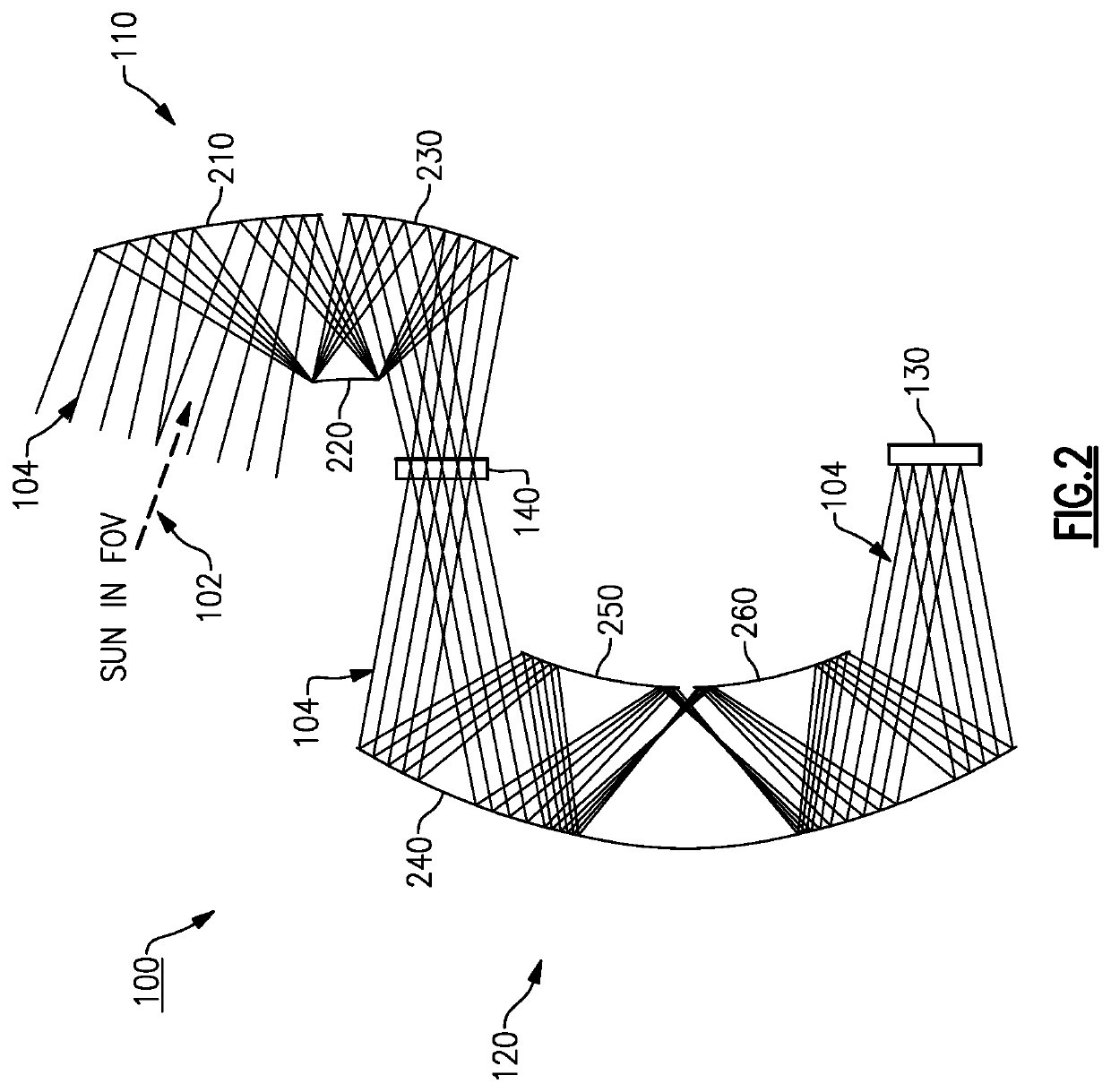
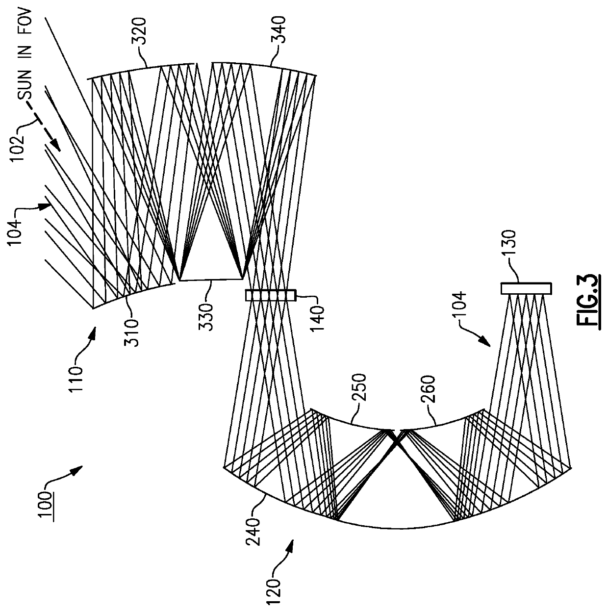
[0028]Aspects and embodiments are directed to an all-reflective solar coronagraph that includes a thermal control subsystem and is configured to continuously image objects, optionally in two spectral bands (e.g., infrared and visible), located as close as 0.5 degrees to the Sun. Embodiments of the solar coronagraph includes an all-reflective relayed optical path, a sensor assembly that may include a visible photosensitive detector (e.g., a focal plane array) and an infrared photosensitive detector, and thermal control subsystem that rejects the direct solar image of the Sun and radiatively exhausts the thermal loads from the mirrors to peripheral radiator panels. As discussed further below, a MEMS-based digital micromirror device (DMD) can be used to reject the solar image. The DMD can be dynamically controlled such that the direct solar image can be rejected with the Sun anywhere in the field-of-view, thereby removing any need for the center of the field of view of the solar corona...


PUM


Abstract

An coronagraph optical system and method for continuously imaging a wide field of view that includes the Sun. Examples of the coronagraph optical system include an all-reflective foreoptics assembly that receives light rays from a viewed scene and a direct solar image of the Sun, a sensor assembly configured to produce an image of the viewed scene, an all-reflective relay optics assembly configured to receive the light rays from the foreoptics assembly and to reflect the light rays to the sensor assembly, and a solar rejection optical component positioned between the foreoptics assembly and the relay optics assembly and dynamically configurable such that the direct solar image of the Sun is reflected away from the relay optics assembly and the light rays are reflected to the relay optics assembly while an entrance aperture of the foreoptics assembly is continuously positioned towards the Sun.

Description

BACKGROUND[0001]Sensing objects close to a solar line of sight (e.g., near the Sun) with a wide field of view and for long periods of time is problematic because conventional telescope optical systems cannot tolerate the extreme solar thermal load on components of the system. As a result, they suffer very significant image quality degradation due to optics misalignments and distortion of the optical surfaces, and thus become unsuitable for their intended purposes.[0002]Existing coronagraphs can sense objects close to the Sun in a narrow field of view and a narrow spectral band, typically for only a transient period of time because the solar thermal load is too intense for the components of the coronagraph to effectively sense the objects without problematic degradation. Such coronagraphs typically implement a significant shield or baffle to block-out a direct solar image of the Sun. Thus, they suffer the restriction of not being able to view certain objects very near the Sun.SUMMARY...

Claims


Application Information

Patent Timeline
IPC IPC(8): G02B17/02G02B17/06G02B26/08G02B27/00
CPCG02B26/0833G02B17/023G02B17/0663G02B27/0081G02B7/181G02B17/0657G02B23/06G02B27/108
Inventor COOK, LACY G.
Owner RAYTHEON CO
Why Eureka
Try Eureka