Image forming apparatus

a technology of image forming apparatus and forming container, which is applied in the direction of electrographic process apparatus, instruments, optics, etc., can solve the problems of increasing the size of the image forming apparatus, increasing the cost of toner, and deteriorating the fluidity of the toner, so as to avoid an increase in the size of the apparatus, the effect of suppressing the temperature of the toner supply container

Active Publication Date: 2019-12-12
CANON KK
View PDF6 Cites 5 Cited by
  • Summary
  • Abstract
  • Description
  • Claims
  • Application Information

AI Technical Summary

Benefits of technology

[0016]To address the above drawbacks, the present invention provides an image forming apparatus that suppresses an increase in the temperature of a toner supply container while avoiding an increase in the size of the apparatus.

Problems solved by technology

An increase in temperature around toner causes a deterioration in fluidity of the toner or causes the toner to solidify in a toner supply container.
To prevent an increase in the temperature of the toners in the toner supply containers 100Y, 100C, 100M, and 100K, cooling by a fan and securing a space for heat insulation are required; however, these measures have drawbacks, such as an increase in costs and an increase in the size of the image forming apparatus.

Method used


Image

  • Image forming apparatus
  • Image forming apparatus
  • Image forming apparatus

Examples


first embodiment

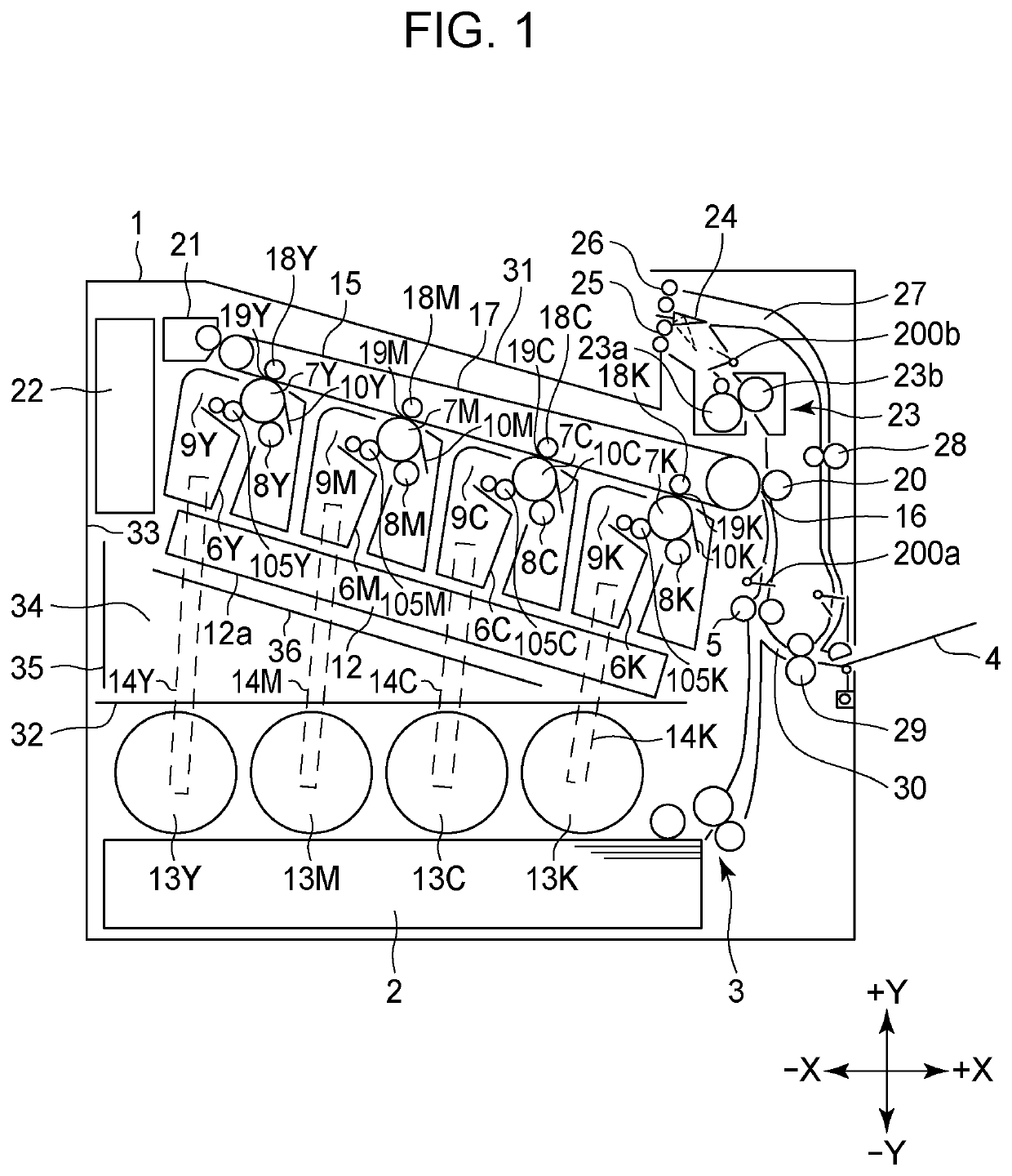
[0031]FIG. 1 is a sectional view of the overall structure of a body 1 of an image forming apparatus. The apparatus according to the first embodiment is a laser beam printer capable of printing a color image on a sheet.

[Sheet Feeding]

[0032]Reference symbol 1 denotes a body of the image forming apparatus, reference symbol 2 denotes a cassette that is attachable and detachable to and from the body 1 and stores a sheet, and reference symbol 3 denotes a sheet feeding portion. Reference symbol 4 denotes a manual sheet feeding portion, and reference symbol 5 denotes a registration roller that adjusts the skew of a sheet. Reference symbol 200a denotes a conveyance sensor that detects passage of a sheet.

[Image Forming Portion]

[0033]The image forming apparatus includes four image forming portions 6Y, 6M, 6C, and 6K corresponding to yellow, magenta, cyan, and black, respectively. Hereinafter, the image forming portions 6Y, 6M, 6C, and 6K are collectively referred to as the image forming portio...

second embodiment

[0053]The printer according to the second embodiment illustrated in FIG. 9 is a monochromatic printer. The printer according to the second embodiment includes one image forming portion 6 and one toner supply container 13 and is substantially the same as the printer according to the first embodiment in terms of other features. Thus, only differences therebetween will be described below.

[0054]The printer according to the second embodiment is the same as the color printer according to the first embodiment from which the image forming portions other than the image forming portion for black are removed. Thus, although the printer is a monochromatic printer, the printer includes the intermediate transfer belt 17 and other components. Using the same body and the same components as those of the color printer according to the first embodiment in the monochromatic printer according to the second embodiment provides an advantage such that it is possible to reduce costs for designing and manufa...


PUM


Abstract

An image forming apparatus is capable of being attached with a toner supply container. The toner supply container stores a toner that is to be supplied to a developing portion. An attachment location of the toner supply container is below a light scanning portion in a vertical direction.

Description

TECHNICAL FIELD[0001]The present invention relates to an image forming apparatus, such as a copier, a printer, or a multifunction device, that forms images by using an electrophotographic system.BACKGROUND ART[0002]An electrophotographic image forming apparatus includes a toner supply container for supplying toner, which decreases with image formation, the toner supply container being detachably attached to a body of the image forming apparatus. An image forming apparatus such as a color machine including a plurality of developing portions includes a plurality of toner supply containers that correspond to the respective developing portions, the toner supply containers being detachably attached to the apparatus. (Japanese Patent Laid-Open Nos. 2014-178398, 2002-244529, 2016-31497, 2014-74890)[0003]An attachment location of a toner supply container in a body of an image forming apparatus varies depending on the image forming apparatus. For example, in the image forming apparatus in FI...

Claims


Application Information

Patent Timeline
Patent Type & Authority Applications(United States)
IPC IPC(8): G03G15/16G03G15/01
CPCG03G15/161G03G15/0121G03G21/1604G03G15/0178G03G15/0867G03G15/0879G03G15/04G03G15/0189G03G21/1676G03G2215/0132G03G15/0868G03G2215/0685
Inventor SUZUKI, KAZUSHISUGITA, TAKESHIKANEKO, TAMOTSUSAITO, HISAHIROMAEBASHI, YOICHIRO
Owner CANON KK
Why Eureka
Try Eureka