
Belt conveyor and system

a belt conveyor and belt technology, applied in the direction of conveyors, transportation and packaging, etc., can solve the problems of high cost and difficulty of large belt conveyors, problems such as problems, goods getting stuck between belt conveyors, etc., and achieves the effect of improving quality and cost, improving manufacturing efficiency, and being convenient to handl

Active Publication Date: 2019-12-19
PACKSIZE
View PDF19 Cites 0 Cited by
  • Summary
  • Abstract
  • Description
  • Claims
  • Application Information

AI Technical Summary

Benefits of technology

The invention relates to a conveyor system where parts of the belt are not sticking out to the sides, allowing two or more conveyors to be placed close to each other. This is achieved by using a holding device that holds the belt and is connected to the frame. The technical effect is that the conveyor system is more compact and efficient in utilizing space.

Problems solved by technology

However large belt conveyors are both expensive and difficult to handle.
Problems could then arise when goods get stuck between belt conveyors, for example goods can get stuck under the belt or on the belt edges.
This could especially be a problem when goods are pushed back and forth transversely over the belt conveyors as could be the case in a box template production machine.
However, then a non-driven section of the conveyor is introduced, which can cause the goods to fail in following transport, such as rotating or slip.
A wide belt creates more than proportionally much friction losses.
This causes the need of more powerful motors and more wear.
A negative side-effect of using a wide belt is furthermore that the solution does not easily react to abnormal changes in the load.
In case a human being step up onto the conveyor, a smaller conveyor run by a smaller motor would not be able to start movement, while a larger might, and thereby causing injury.

Method used


Image

  • Belt conveyor and system
  • Belt conveyor and system
  • Belt conveyor and system

Examples


Embodiment Construction

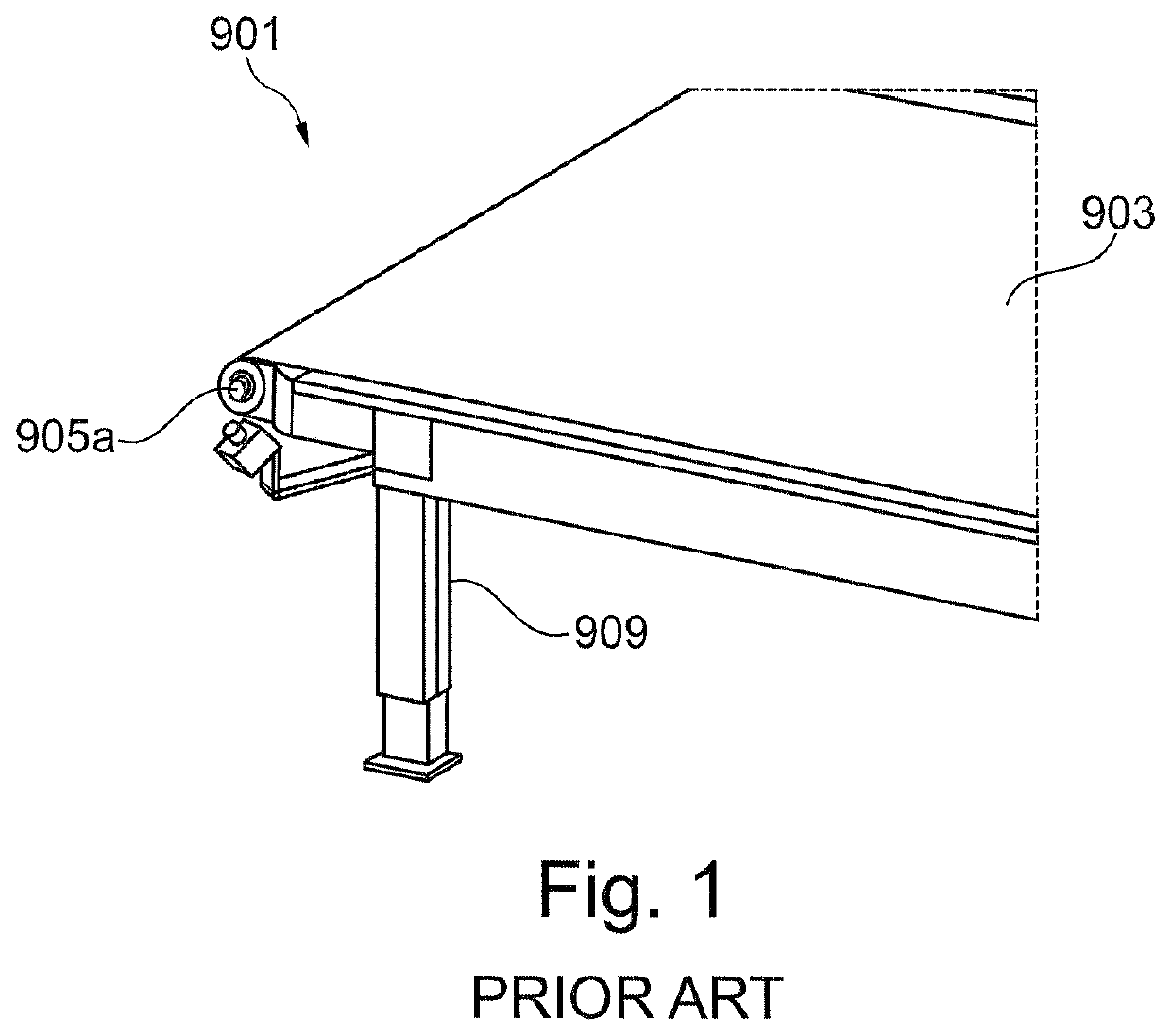
[0026]FIG. 1 shows schematically a perspective view of a part of a conventional belt conveyor 901. The belt conveyor 901 comprises an endless loop of belt 903 which is rotating about two pulleys 905a (905b not shown). The belt conveyor 901 comprises further a frame 909 holding said two pulleys 905a and a belt supporting device configured for supporting the belt between the two pulleys while allowing the belt to slide over the belt supporting device.

[0027]When positioning two of these conventional belt conveyors side by side for the purpose of achieving a larger combined belt conveyor problems may arise as described above. For example parts of the frame 909 and the pulleys 905a in conventional belt conveyors are often protruding out on the sides of the belt conveyor. Hereby there will be a gap between the separate belts when providing two or more conventional belt conveyors side by side. Furthermore, in applications where goods are transported transverse to the belt direction when de...


PUM


Abstract

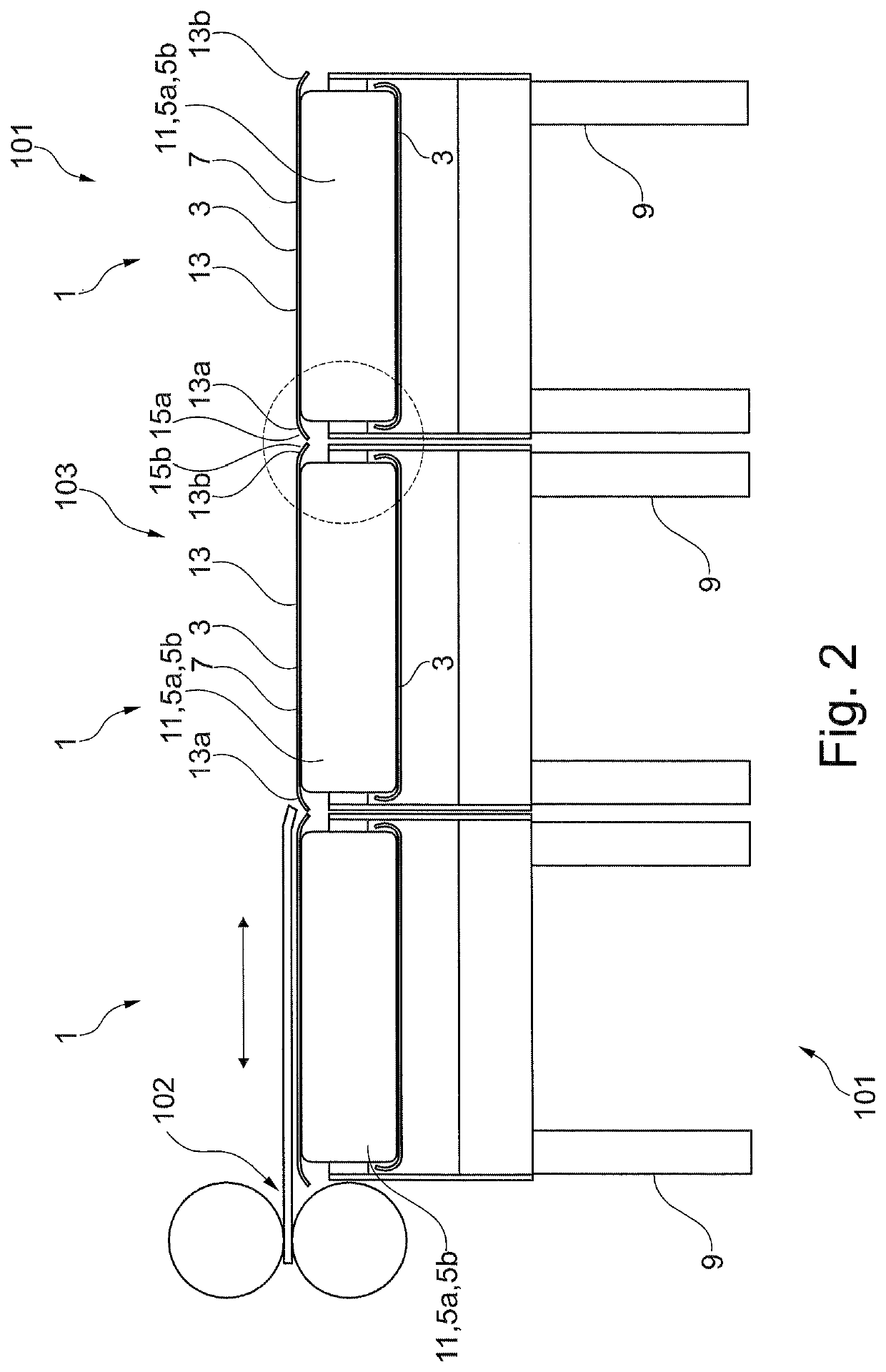
A belt conveyor (1), a belt conveyor system and a box template production system. Said belt conveyor comprising an endless loop of belt (3) which is rotating about at least two pulleys (5a, 5b) comprised in the belt conveyor, whereby different parts of the belt (3) will constitute an upper surface (7) for transporting goods during run, the belt conveyer (1) further comprising a frame (9) holding said at least two pulleys (5a, 5b) and a belt supporting device (11) configured for supporting the belt between the at least two pulleys while allowing the belt (3) to slide over the belt supporting device (11), wherein said belt (3) comprises a substantially plane middle part (13) along the length of the belt and two edge areas (13a, 13b), one provided on each side of the middle part (13), wherein at least one of said edge areas (13a, 13b) is sloped towards an opposite part of the belt in the endless loop at least when said at least one edge area (13a, 13b) constitutes a part of the upper surface of the belt.

Description

TECHNICAL FIELD OF THE INVENTION[0001]The present invention relates to a belt conveyor, a belt conveyor system and a box template production system.RELATED ART[0002]Belt conveyors are commonly used for the transportation of goods. Different sizes of belt conveyors are available. However large belt conveyors are both expensive and difficult to handle.SUMMARY[0003]An object of the present invention is to provide an improved and more flexible belt conveyor.[0004]This is achieved by a belt conveyor and a belt conveyor system according to the independent claims.[0005]In one aspect of the invention a belt conveyor is provided comprising an endless loop of belt which is rotating about at least two pulleys comprised in the belt conveyor, whereby different parts of the belt will constitute an upper surface for transporting goods during run, the belt conveyer further comprising a frame holding said at least two pulleys and a belt supporting device configured for supporting the belt between th...

Claims


Application Information

Patent Timeline
Patent Type & Authority Applications(United States)
IPC IPC(8): B65G15/46B65G15/62
CPCB65G15/46B65G15/62B65G15/64B65G15/56B65G2812/02128B65G2812/02168
Inventor PETTERSSON, NIKLAS
Owner PACKSIZE
Learn More