Eureka AIR delivers breakthrough ideas for toughest innovation challenges, trusted by R&D personnel around the world.

Method for forming aluminum film

Active Publication Date: 2019-12-26
MITSUBISHI ELECTRIC CORP
View PDF0 Cites 0 Cited by
  • Summary
  • Abstract
  • Description
  • Claims
  • Application Information

AI Technical Summary

Benefits of technology

The present invention provides a technique for making an aluminum film by sputtering that has high flatness and minimal cavities. This technique helps to create a more uniform and high-quality film.

Problems solved by technology

Thus, a film, when formed on a recess with a large step through normal sputtering, is not easily deposited on the bottom of the recess, and is easily deposited near the opening of the recess.
This combining tends to generate cavities inside the film deposited in the recess, and tends to generate a dent on the surface of the film.
As such, normal sputtering is disadvantageous in forming of an aluminum film on a semiconductor substrate having a rough surface.
However, heating at such a temperature leads to coagulation, and degradation in the device performance of a semiconductor device.
Long-throw sputtering has an excessively low rate of film formation.
Hence, long-throw sputtering is disadvantageous in forming of a thick aluminum film of the order of microns.
Aluminum-film formation through CVD, which increases running costs, tact time (or takt time) and process steps, is undesirable.
Accordingly, both of these methods lead to cost increase and increase in the number of process steps due to reduction in film formation efficiency.

Method used


Image

  • Method for forming aluminum film
  • Method for forming aluminum film
  • Method for forming aluminum film

Examples


Embodiment Construction

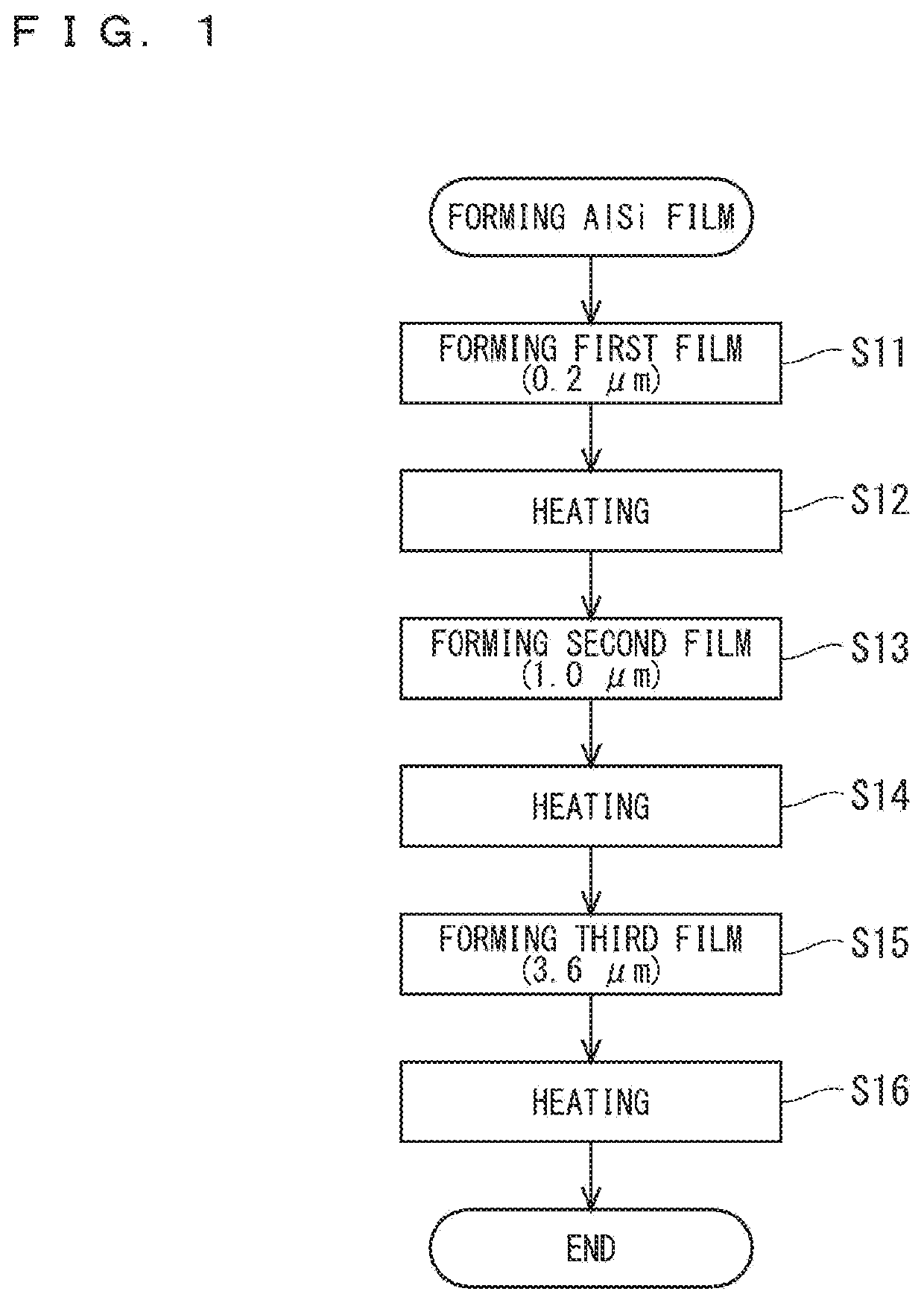
[0025]FIG. 1 is a flowchart illustrating a method for forming an aluminum film according to a preferred embodiment of the present invention. The material of the aluminum film is aluminum or an aluminum compound. An aluminum film of AlSi is formed in the preferred embodiment. The aforementioned material is used as a target to be sputtered, and AlSi is used for instance. The preferred embodiment employs normal sputtering, which is a type of sputtering, and employs a substrate-to-target distance of, for instance, 45 mm. The preferred embodiment describes forming an aluminum film having high flatness, without employing a long-throw sputtering method.

[0026]Step S11 is forming a first film. More specifically, the first film is formed by sputtering the target onto a substrate, which will be described later on. Step S12 is reflowing the first film by heating the first film. As such, steps S11 and S12, together, can be referred to as the first reflow sputtering.

[0027]Step S13 is forming a se...


PUM

PropertyMeasurementUnit
Lengthaaaaaaaaaa
Lengthaaaaaaaaaa
Thicknessaaaaaaaaaa

Abstract

Provided is a technique of forming an aluminum film that has high flatness and less cavities. Step S11 is forming a first film having a thickness that is equal to or greater than 0.1 μm and less than 1 μm, by sputtering a material onto a substrate. Step S12 is reflowing the first film by heating the first film. Step S13 is forming a second film by sputtering the material onto the first film that has been reflowed. Step S14 is reflowing the second film by heating the second film. Step S15 is forming a third film by sputtering the material onto the second film that has been reflowed. Step S16 is reflowing the third film by heating the third film.

Description

BACKGROUND OF THE INVENTIONField of the Invention[0001]The present invention relates to a method for forming an aluminum film.Description of the Background Art[0002]In the manufacture of semiconductor devices, forming aluminum (Al) or an aluminum compound (e.g., AlSi, AlCu, or AlSiCu) through sputtering is a publicly known technique. Hereinafter, a film of aluminum or of an aluminum compound is also referred to as an aluminum film.[0003]Hot sputtering and reflow sputtering are publicly known as sputtering methods. Hot sputtering includes heating an object (e.g., a substrate on which transistor cells are formed) to undergo film formation while forming a film through sputtering (hereinafter, also referred to as film formation). Reflow sputtering includes heating an object after film formation through sputtering, thus reflowing the formed film.[0004]Reflow sputtering is used in the techniques described in Japanese Patent Application Laid-Open No. 2005-347313 and Japanese Patent Applica...

Claims


Application Information

Patent Timeline
IPC IPC(8): C23C14/16C23C14/34
CPCH01L21/02631C23C14/165C23C14/3421C23C14/5806H01L21/76882H01L21/2855H01L23/53219H01L2224/05624
Inventor TOKURA, YUJI
Owner MITSUBISHI ELECTRIC CORP
Why Eureka
Eureka Blog
Learn More