Eureka AIR delivers breakthrough ideas for toughest innovation challenges, trusted by R&D personnel around the world.

R-t-b based permanent magnet

Active Publication Date: 2018-10-11
TDK CORPARATION
View PDF4 Cites 0 Cited by
  • Summary
  • Abstract
  • Description
  • Claims
  • Application Information

AI Technical Summary

Benefits of technology

The present invention provides a special permanent magnet with low coercive force and magnetizing field, and high residual magnetic flux density and minor curve flatness even at low magnetizing fields. This makes it easy to control the magnetization process and achieve the desired outcome.

Problems solved by technology

When the magnetizing field Hmag becomes large, there is a problem that it exceeds the upper limit of the magnetic field that can be applied by a stator coil of the motor.
However, even if the minor curve flatness is high in the second and third quadrants, but is low in the first and fourth quadrants, it becomes difficult to magnetize to the desired magnetization state when the successive increase of magnetism is performed.

Method used


Image

  • R-t-b based permanent magnet
  • R-t-b based permanent magnet
  • R-t-b based permanent magnet

Examples


examples

[0142]Hereinafter, the present invention will be described in more detail referring to Examples. However, the present invention is not limited thereto.

examples 1 to 10

[0143]Firstly, raw materials were blended so as to obtain the R-T-B based permanent magnet having the composition shown in Table 1, raw materials thereof were melted and then cast by a strip casting method to obtain a flaky raw material alloy.

[0144]Next, the HDDR process was performed to these raw material alloys. In the HDDR process, hydrogenation was performed by maintaining at 800° C. in an H2 gas atmosphere, dehydrogenation treatment was performed at 800° C. until the partial pressure of H2 gas in the atmosphere becomes one Pa or less, and then cooling was performed to obtain an HDDR alloy.

[0145]Next, hydrogen pulverization was carried out by the following. After hydrogen was absorbed to the HDDR alloy at room temperature, the heat treatment at 300° C. for one hour in an Ar atmosphere was performed. Then, it was once cooled to room temperature and the heat treatment was again performed at 300° C. for one hour in a vacuum atmosphere. Thereafter, the obtained pulverized material w...

examples 11 to 20

[0165]Samples were prepared in the same manner as in Example 5 or 6, except that Nd as R included in the R-T-B based permanent magnet was partly substituted with Y or Ce as R2 at the ratio shown in Table 2. And the samples were evaluated by the same method as in Example 5 or 6. The results of composition analysis of the samples of Examples 11 to 20 are shown in Table 1. Also, x and y were calculated from composition analysis results, and the relation between x and y was plotted in FIG. 3. The evaluation results of the samples of Examples 11 to 20 are shown in Table 3.

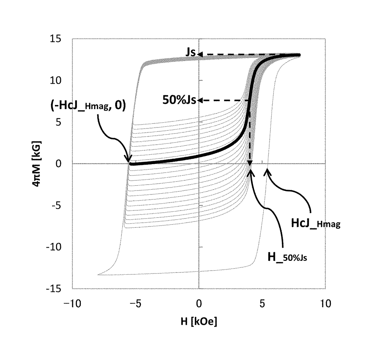
TABLE 3R-T-B based magnetSintered magnetMain phase R2T14BAreaRSinteringCarbonratio ofR2Rare-earthtemperatureconcentrationvoidsElementcomposition(° C.)(ppm)(%)R1typexEx. 5Nd10087558100Nd—0.000Ex. 11Nd90Y1087558300NdY0.090Ex. 12Nd70Y3090057900NdY0.290Ex. 13Nd50Y5090058000NdY0.480Ex. 14Nd30Y7090058400NdY0.680Ex. 15Nd10Y9090058000NdY0.880Ex. 6Nd10087553800Nd—0.000Ex. 16Nd90Ce1087553300NdCe0.090Ex. 17Nd70Ce3090054200NdCe0.29...


PUM

PropertyMeasurementUnit
Massaaaaaaaaaa
Fractionaaaaaaaaaa
Fractionaaaaaaaaaa

Abstract

An object of the present invention is to provide an R-T-B based permanent magnet having a low coercive force and a low magnetizing field, and having a high residual magnetic flux density and a high minor curve flatness even in the low magnetizing field. Provided is an R-T-B based permanent magnet including a main phase including a compound having an R2T14B type tetragonal structure and a grain boundary phase existing between the main phases, in which R is at least one rare earth element including scandium and yttrium, T is at least one transition metal element including iron, or at least two transition metal elements including iron and cobalt, the grain boundary includes an R-T-B—C based compound having a higher R concentration, B concentration and C concentration than that of the main phase and having a lower T concentration than that of the main phase.

Description

BACKGROUND OF THE INVENTION1. Field of the Invention[0001]The present invention relates to an R-T-B based permanent magnet. More particularly, the present invention relates to a permanent magnet suitable for a variable magnetic flux magnet constituting a variable magnetic force motor.2. Description of the Related Art[0002]A permanent magnet synchronous motor, which is capable of saving energy by inverter control and is highly efficient, has been used as a power unit of consumer, industrial and transportation equipment. However, according to the permanent magnet synchronous motor in which the magnetic flux of the permanent magnet is constant, driving at a wide rotation speed becomes difficult since the induced voltage increases in proportion to the rotation speed. For this reason, in order to prevent the induced voltage from the power supply voltage or more in a middle or high speed range and under a light load, a technique called a field weakening control, which cancels the magnetic...

Claims


Application Information

Patent Timeline
IPC IPC(8): H01F1/057C22C38/00C22C38/10H01F7/02
CPCH01F1/057C22C38/005C22C38/10H01F7/02C22C2202/02H01F1/0577H01F41/0253H01F41/0266
Inventor TAKEDA, KEIJIMIYAZAKI, SHOTA
Owner TDK CORPARATION
Why Eureka
Eureka Blog
Learn More