Design method of one-dimensional membrane cavity optical interleaver with unequal bandwidth
A multiplexer and membrane cavity technology, which is applied in the direction of instruments, light guides, optics, etc., can solve the problems of complex design method and structure, fixed duty ratio, and difficulty in realization, and achieve the effect of simple structure, easy manufacture, and simple method
- Summary
- Abstract
- Description
- Claims
- Application Information
AI Technical Summary
Problems solved by technology
Method used
Image

Examples
Embodiment 1
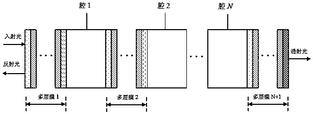
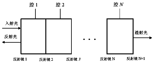
[0028] see Figure 1 to Figure 5 , the design method of the one-dimensional membrane cavity type optical interleaver with unequal bandwidth is characterized in that: the multilayer membrane structure between the dielectric cavities is equivalent to a mirror, and the simplified structure of the multi-cavity mirror cascade structure is obtained ; Introduce the z-transform in the theory of digital signal processing to obtain the expression of the reflection transfer function of the simplified structure, on this basis, combine the design method of the Butterworth digital filter, and use the genetic algorithm to obtain the optimal reflection coefficient of each mirror; finally The multi-layer film structure between the dielectric cavities is constructed according to the optimal reflection coefficient to realize the design of a one-dimensional film cavity type optical interleaver with unequal bandwidth; let the optical thickness of each dielectric cavity nd=c / 2Δf, c is the speed of l...
Embodiment 2
[0037] This embodiment is basically the same as Embodiment 1, and the special features are as follows:
[0038] 1. The simplified cascaded structure of symmetrical membrane cavity, the reflection transfer function expression
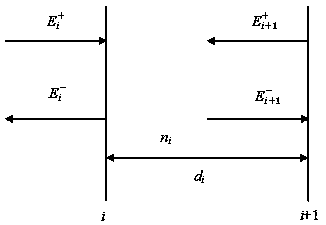
[0039] The electric field distribution between mirror i and i+1 is as follows image 3 shown, where and denote the amplitudes of electric field vectors propagating to the right from the left-hand sides of mirrors i and i+1, respectively, and denote the amplitudes of the electric field vectors propagating to the left on the left-hand sides of mirrors i and i+1, respectively, r i and t i denote the amplitude reflection coefficient and transmission coefficient of mirror i respectively, n i d i is the optical thickness of the dielectric cavity between mirrors i and i+1, then the phase is where f is the frequency of the incident light, c is the speed of light,
[0040] Depend on image 3 Available:
[0041]
[0042] By analogy, for the case...
Embodiment 3
[0054] The design method of this one-dimensional membrane cavity type unequal bandwidth optical interleaver is as follows: Here, the specific design of unequal bandwidth optical interleaver with 100GHz, duty ratio 1:5, and isolation <-30dB is used to illustrate. By design method:
[0055] Step 1: Using the Butterworth filter design principle in digital signal processing, the reflection transfer function of the Butterworth digital filter that meets the requirements of the spectral characteristics can be obtained as:
[0056]
[0057] The second step: it can be obtained from formula (6), the order of the filter is 3rd order;
[0058] Step 3: Since the order of the filter is 3, there are 4 equivalent mirrors. Since it is a symmetrical structure, the reflection coefficient of the mirror can be expressed as r 1 , r 2 , r 2 , r 1 ;
[0059] Step 4: Calculate the reflection transfer function of the simplified structure according to formulas (3) and (4):
[0060]
[0061] ...
PUM
 Abstract
Description
Claims
Application Information